Showing posts with label arduino. Show all posts

Deep dive into how the Teensy microcontroller interacts with the Arduino library

The Arduino language lets you program microcontrollers at a high level, controlling I/O pins without worry about exactly how the microcontroller works. But what's really going on behind the scenes? For my current project, I'm using a Teensy 3.6,1 a development board packaged in a breadboard-compatible 48-pin module that is considerably smaller than a classic Arduino.2 The Teensy uses a fairly powerful microcontroller, a 32-bit ARM processor running at 180 megahertz, and it is (mostly) compatible with the Arduino programming environment. I wanted to understand the low-level hardware better, so I investigated the implementation of one of the Arduino functions. Specifically, this post explains exactly how the analogWrite() function works in the Teensy 3.6. Disclaimer: this blog post goes into excessive detail on an obscure subject, so feel free to stop reading now :-)

An Arduino (top) and Teensy 3.6 (bottom).

An Arduino (top) and Teensy 3.6 (bottom).

analogWrite(): creating a PWM output

The Arduino IDE lets you quickly create an application using functions that abstract away the microcontroller's implementation details. In comparison, if you program a microcontroller directly, its hardware functions are activated by accessing special memory locations that act as control registers. There may be thousands of registers, different for each microcontroller, and described in thousand-page manuals, so programming a microcontroller directly can be daunting.

Using the Arduino library, you can put a voltage on an output pin with the analogWrite(pin, value) function. You specify a value between 0 and 256, where 0 is completely off and 256 is completely on and the library takes care of the details. For instance, analogWrite(pin, 64) produces an output value of 25% (i.e. 64/256). You might expect this would produce an analog voltage at 25% of the maximum, but 
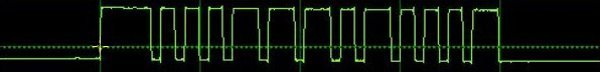
despite the function's name, the output is not analog. Instead it is a digital pulse-width modulated (PWM) signal, which averages out to the desired value.3 As the oscilloscope trace below shows, the output switches between full-on and full-off, remaining on 25% of the time.4 Even though it doesn't produce a true analog output, the analogWrite function is useful for many tasks, such as controlling LED brightness.

Oscilloscope output showing the output from analogWrite().

Oscilloscope output showing the output from analogWrite().

The diagram below shows how the output changes with different analogWrite values, from 0 (completely off) to 256 (completely on). The main point is that the output is really digital, with a larger input parameter causing the output to be on for a larger fraction of the time. This technique is called Pulse Width Modulation (PWM), since the width of the pulse changes with the input.

Examples of different analogWrite values, from 0 to 256.

Examples of different analogWrite values, from 0 to 256.

The diagram below illustrates how the microcontroller produces the PWM output. Internally, a timer repeatedly counts from 0 to 255, generating a counter value. Each time the timer starts at 0, the output is set high. When the timer matches the specified value (64 in this case), the output goes low. Thus, the match value controls how long the output remains high in each cycle; the larger the value, the longer the output remains high. The timer increments every 8 microseconds, so the total cycle length is 2048 microseconds, yielding a frequency of 490 Hz.

A PWM output is implemented by a timer and a match value.

A PWM output is implemented by a timer and a match value.

The analogWrite function is sufficient for most purposes, but how does it work at the microcontroller register level? The manual for the Teensy's MK66FX1M0 processor explains how the chip's registers work, but is 2237 pages long. (I've extracted the relevant bits and give references to manual sections if you want to know more.) The code for the Teensy implementation of analogWrite is in a file called pins_teensy.c. Because the code supports multiple processors, it is full of #ifdefs; the Teensy 3.6 code is selected by the __MK66FX1M0__ and KINETISK5 defines, specifying the processor type and family. The code contains a bunch of case statements to handle all the different types of PWM pins. I'm using pin 30 in my example, which is defined in that file as FTM2_CH1_PIN (FlexTimer 2 Channel 1 pin). (I'll explain below why this timer is pin 30.)

The code to handle that pin is:

cval = ((uint32_t)val * (uint32_t)(FTM2_MOD + 1)) >> analog_write_res;
FTM2_C1V = cval;
FTM_PINCFG(FTM2_CH1_PIN) = PORT_PCR_MUX(3) | PORT_PCR_DSE | PORT_PCR_SRE;

As you can see, this code is much more complex than the analogWrite() call. In brief, the first line computes the counter value (match value) at which the output should go to 0. The second line stores this value into the timer control register. The third line configures pin 30 for the timer output. Next, I'll explain each of these lines in more detail.

The first line handles the difference between the conceptual timer (counting from 0 to 255) and the physical implementation of the timer, which is 16 bits and counts at a much higher rate. To match the Arduino's PWM frequency (490 Hz), the Teensy timer counts to 61439. This line scales the input value (0 to 256) to the desired range (0 to 61440). Specifically, the hardware register FTM2_MOD (timer 2 modulo) holds 61439, the value that this timer counts to.6 Multiplying the input value by 61440 and dividing by 256 scales the input value to the new range. (The value 8 for analog_write_res indicates 8 bits of count resolution, i.e. 256.)7

The next line of code stores this value into timer 2's Channel 1 Value register FTM_C1V,8 which controls the pulse width. This register holds the "match value"; when the timer counter reaches this value, the output drop to 0.

The third line configures pin 30 for the output from the timer. The FTM_PINCFG macro handles pin configuration, which in this case updates the configuration for pin 30 (CORE_PIN30_CONFIG).11 The PORT_PCR_MUX(3) macro selects the pin's function from the pin multiplexer, which I'll explain in the next section.10 The PORT_PCR_DSE option sets Drive Strength Enable, enabling high-current output. The PORT_PCR_SRE option sets Slew Rate Enable, slowing the pin's slew rate (how fast it changes value).9 These values are combined and stored in the appropriate bit fields of the Pin Control Register, shown below. (The macros ensure that each value goes into the right position.)

This diagram shows how multiple fields are packed into a Pin Control Register. (From Section 12.5.1 of the manual.)

This diagram shows how multiple fields are packed into a Pin Control Register. (From Section 12.5.1 of the manual.)

Filling in the macros, the original analogWrite(30, 64) call becomes:

*(uint32_t *)0x400B8018 = 15360;
*(uint32_t *)0x4004A04C = 0x344;

Thus, in the end, the analogWrite call turns into two stores to microcontroller registers.

Determining the pin and its function

Pin configuration is more complex than you might expect. The problem is that the processor chip has 144 pins (in a 12×12 grid), but the microcontroller provides a much larger number of functions. The solution is that each pin has up to 8 different multiplexed functions, and you can select one of these functions for each pin. Thus, you can't use all the features of the chip at the same time, but hopefully you can use the features you need.

The chip has a 12×12 grid of solder balls on the bottom.
(Photo from Digi-Key.)

The chip has a 12×12 grid of solder balls on the bottom. (Photo from Digi-Key.)

In the example I'm using GPIO pin 30, but this pin number is part of the Arduino API: the microcontroller has no pin 30. So how does pin 30 get a meaning? In this section, I explain how pin 30 maps onto a physical pin of the microcontroller (pin D11 in this case) associated with a PWM timer (FlexTimer 2 channel 1 in this case).

The function of each Teensy pin is documented, but I wanted to figure out "from scratch" what GPIO pin 30 means. Looking at the schematic shows the Teensy's pin 30 is connected to pin D11 of the processor, which is labeled "PTB19". (Processor pins are labeled with a letter and number corresponding to the pin's grid position.)

Detail of the Teensy 3.6 schematic showing microcontroller pin D11 is connected to Teensy GPIO pin 30.

Detail of the Teensy 3.6 schematic showing microcontroller pin D11 is connected to Teensy GPIO pin 30.

Chapter 11 of the manual lists the names and functions for each pin (excerpted below). As mentioned earlier, each physical pin supports multiple functions. Pin D11 has the official name "PTB19" and has seven different functions assigned to it: Touch Screen, GPIO PorT B, CAN bus, FlexTiMer FTM2_CH1 (that we're using), I2S audio, FlexBus, and FlexTiMer 2 Quadrature Decoder.

This excerpt from the manual shows the functions that can be assigned to pin D11.

This excerpt from the manual shows the functions that can be assigned to pin D11.

Each pin has a multiplexer (MUX) that selects which function is assigned to the pin. In order to use the timer with pin D11, the pin configuration register (PCR) for D11 must be configured to assign function 3 to this pin. This was done with the macro discussed earlier, PORT_PCR_MUX(3). Thus, when an analogWrite is performed, the pin is configured to use the appropriate timer.

Initialization

Another piece necessary to make this work is the Teensy's initialization code. The main routine in main.cpp calls _init_Teensyduino_internal_(), which performs the necessary register initialization. The timer 2 initialization code is

FTM2_CNT = 0;
FTM2_MOD = DEFAULT_FTM_MOD;
FTM2_C0SC = 0x28;
FTM2_C1SC = 0x28;
FTM2_SC = FTM_SC_CLKS(1) | FTM_SC_PS(DEFAULT_FTM_PRESCALE);

This sets the initial counter value to 0 and sets the modulo value (maximum count) to 61439 as discussed earlier. The FTM2_C0SC and FTM2_C1SC lines enable PWM mode. The FTM2_SC line sets up the timer clock.12

The last piece is how the code knows the processor type. To support multiple processor types, the files are full of #ifdefs, but where do these get defined? The answer is that the board type and CPU speed are set in the Arduino IDE. The IDE uses these settings to generate flags that are passed to the compiler when compiling the code. The relevant lines for the Teensy 3.6 are in the file hardware/teensy/avr/boards.txt:

teensy36.build.flags.defs=-D__MK66FX1M0__ -DTEENSYDUINO=153
teensy36.menu.speed.180.build.fcpu=180000000

Conclusion

At this point we've reached the foundation. To summarize, the board that you select in the Arduino IDE causes various flags to be passed to the C++ compiler. These flags, in turn, select numerous definitions of registers for that processor, along with the appropriate code. The result is that a function call such as analogWrite(30), acting on an abstract pin 30, gets converted to operations on special microcontroller registers, causing the microcontroller's circuitry to output the desired signal.

It may seem like magic that high-level operations end up doing the right thing across a wide range of microcontrollers, but this is one of the key accomplishments of the Arduino ecosystem. If you really need to know what's going on, I've shown how these abstractions can be unwrapped. But for the most part, the complexity underneath can fortunately be ignored.

I announce my latest blog posts on Twitter, so follow me @kenshirriff. I also have an RSS feed. I wrote about Arduino PWM and its registers in detail here if you want to know more about PWM. Thanks to Paul Stoffregen for answering my questions about Teensy.

Notes and references

  1. Why am I using a Teensy 3.6 instead of a newer model? Because the more recent Teensy 4.1 was out of stock. 

  2. There are also Arduino models in the DIP form factor, such as the Arduino Nano and Arduino Micro. Arduino also has high-power models such as the 32-bit ARM-based Arduino Portenta

  3. The Teensy 3.6 has two digital-to-analog converter (DAC) outputs. For those two pins, the analogWrite() function produces a genuine analog voltage, not a PWM output. 

  4. The PWM output has a period of 2048 µs, yielding a frequency of about 490 Hertz. The output is controlled in units of 8 µs, so an input value of 1 yields a pulse width of 8 µs, an input of 64 yields a pulse width of 512 µs and so forth. 

  5. I tried to sort out what "Kinetis" means. NXP has many different microcontrollers and Kinetis is their family of 32-bit mixed-signal ARM Cortex microcontrollers, introduced in 2010. The Kinetis family includes the high-performance K series and the low-power L series. The Teensy 3.x boards use the Kinetis K series and have the preprocessor variable KINETISK defined, while the Teensy LC board uses a Kinetis L processor and has KINETISL defined. 

  6. The variable FTM2_MOD is defined as the address (400B8008) of the FTM2 modulo register in kinetis.h. Why is the modulo set to 61439? The goal is to make the PWM period match the Arduino's 2048 µs period (approximately 490 Hertz). To see how this happens, start with the Teensy's clock frequency (F_CPU) of 180 MHz. kinetis.h sets the bus frequency F_BUS to 60 MHz based on this. Then pins_teensy.c uses this for the timer frequency F_TIMER. For a frequency of 60 MHz, pins_teensy.c sets DEFAULT_FTM_MOD to 61439 and DEFAULT_FTM_PRESCALE to 1. This prescale value causes the timer to divide its input frequency by 2, so the timer runs at 30 megahertz. At this frequency, 61440 ticks will take 2048 µs as desired.

    Figuring out the address for FTM_MOD2 is more confusing than I expected. If you look at the memory map in the manual (Section 45.4.2), the address for FTM2_MOD is 4003A008 (Peripheral bridge 0), but the Teensy uses address 400B8008 (Peripheral bridge 1, Table 5-3), see kinetis.h. It turns out that the chip has two paths for accessing peripherals: AIPS0 and AIPS1. The timer can be accessed through both paths, but with different register addresses.

    Another confusing thing is that if you try to access FTM2_MOD through the first address, the Teensy will crash. The reason is that the microcontroller lets you conserver power by turning off the clock to each module, a function called "clock gating". If you try to access a peripheral when the clock is disabled, the system terminates with an error. The two different paths to the timer are controlled by separate clocks. Specifically, access through AIPS0 is enabled through System Clock Gating Control Register 6 (SIM_SCGC6, section 13.2.16), while access through AIPS1 is enabled through SIM_SCGC3 (sections 13.2.13). The Teensy startup code enables timer FTM2 through clock gating register SIM_SCGC3 (for AIPS1) but not SIM_SCGC6 (for AIPS0). Thus, accessing the timer through AIPS1 works, but accessing it through AIPS0 crashes. This thread has more information. 

  7. By default, the value to analogWrite() can range from 0 to 256, i.e. 8 bits of resolution. However, the resolution can be changed by calling analogWriteResolution. Higher resolution gives finer-grain control over the PWM width.

    The Teensy extensions to Arduino include a function analogWriteFrequency(), which provides a more convenient way of modifying the PWM frequency. 

  8. The Register Descriptions section (45.4.2) describes the memory address for each register. FTM2_C1V is the "Channel Value" at address 4003A018. Section 45.4.7 explains that this register holds the 16-bit counter value that the timer matches against. 

  9. On my breadboard, a signal has a rise time of 7.5 nanoseconds with slew rate disabled and 15 nanoseconds with slew rate enabled. The fast signal has a bunch of ringing, while the slower signal rises smoothly. 

  10. The Pin Control Register is described in section 12.5.1 with details in chapter 11, Signal Multiplexing and Signal Descriptions. 

  11. The macro FTM_PINCFG(FTM2_CH1_PIN) turns into CORE_PIN30_CONFIG, the appropriate configuration register. This is defined in core_pins.h as PORTB_PCR19. The manual (section 12.5) specifies that PORTB_PCR19 (Port B Pin Control Register 19) has address 4004A04C. 

  12. Register constants FTM2_C0SC and FTM2_C1SC are set to 0x400B800C and 0x400B8014 respectively in kinetis.h. The manual defines these addresses (section 45.4.2) as 4003_A00C and 4003_A014. (The differences are because the timer can be accessed through a different path (Peripheral Bridge 1) at address 400B_8xxx.) These registers are Channel 0/1 Status and Control, discussed in manual section 45.4.6. Each register has 7 bit fields that control the timer function. The initialization value 0x28 selects Edge-Aligned PWM with high-true pulses.

    Register constant FTM2_SC (timer 2 Status and Control) has address 400B8000 in the code and 4003A000 in the manual. Its fields are described in manual section 45.4.3. FTM_SC_CLKS(1) sets the CLKS field to use the system clock as the timer input. FTM_SC_PS sets the prescale to divide the clock by 2, as discussed earlier. 

Decoding an air conditioner control's checksum with differential cryptanalysis

Back in 2009 I wrote an Arduino library (IRRemote) to encode and decode infrared signals for remote controls. I got an email recently from someone wanting to control an air conditioner. It turns out that air conditioner remote controls are much complicated than TV remote controls: the codes are longer and include a moderately complex checksum. My reader had collected 35 signals from his air conditioner remote control, but couldn't figure out the checksum algorithm. I decided to use differential cryptanalysis to figure out the checksum, which was overkill but an interesting exercise. In case anyone else wants to decode a similar remote control, I've written up how I found the algorithm.

My IR remote library can be used with the Arduino to send and receive signals. (This is not the air conditioner remote.)

My IR remote library can be used with the Arduino to send and receive signals. (This is not the air conditioner remote.)

The problem is to find a checksum algorithm that when given three bytes of input (left), computes the correct one byte checksum (right).

10100001 10010011 01100011 => 01110111
10100001 10010011 01100100 => 01110001
10100001 10010011 01100101 => 01110000
10100001 10010011 01100110 => 01110010
10100001 10010011 01100111 => 01110011
10100001 10010011 01101000 => 01111001
10100001 10010011 01101001 => 01111000
10100001 10010011 01101010 => 01111010
10100001 10010011 01101011 => 01111011
10100001 10010011 01101100 => 01111110
10100001 10010011 01101101 => 01111111
10100001 10010011 01101110 => 01111100
10100001 10010011 01101111 => 01111101
10100001 10010011 01110001 => 01100100
10100001 10010011 01110010 => 01100110
10100001 10010011 01110011 => 01100111
10100001 10010011 01110100 => 01100001
10100001 10010011 01110101 => 01100000
10100001 10010011 01110111 => 01100011
10100001 10010011 01110111 => 01100011
10100001 10010011 01111000 => 01101001
10100001 10010011 01101000 => 01111001
10100001 00010011 01101000 => 11111001
10100001 00010011 01101100 => 11111110
10100001 10010011 01101100 => 01111110
10100001 10010100 01111110 => 01101011
10100001 10000010 01101100 => 01100000
10100001 10000001 01101100 => 01100011
10100001 10010011 01101100 => 01111110
10100001 10010000 01101100 => 01111100
10100001 10011000 01101100 => 01110100
10100001 10001000 01101100 => 01101100
10100001 10010000 01101100 => 01111100
10100001 10011000 01101100 => 01110100
10100010 00000010 11111111 => 01111110

The idea behind differential cryptanalysis is to look at the outputs resulting from inputs that have a small difference, to see what patterns emerge (details). Finding air conditioner checksums is kind of a trivial application of differential cryptanalysis, but using differential cryptanalysis provides a framework for approaching the problem. I wrote a simple program that found input pairs that differed in one bit and displayed the difference (i.e. xor) between the corresponding checksums. The table below shows the differences.

000000000000000000000001 : 00000001
000000000000000000000010 : 00000010
000000000000000000000010 : 00000011
000000000000000000000100 : 00000100
000000000000000000000100 : 00000110
000000000000000000000100 : 00000111
000000000000000000001000 : 00001100
000000000000000000001000 : 00001110
000000000000000000001000 : 00001111
000000000000000000010000 : 00010000
000000000000100000000000 : 00001000
000000000001000000000000 : 00011000
000000001000000000000000 : 10000000

The first thing to notice is that changing one bit in the input causes a relatively small change in the output. If the checksum were something cryptographic, a single bit change would entirely change the output (so you'd see half the bits flipped on average). Thus, we know we're dealing with a simple algorithm.

The second thing to notice is the upper four bits of the checksum change simply: changing a bit in the upper four bits of an input byte changes the corresponding bit in the upper four bits of the output. This suggests that the the three bytes are simply xor'd to generate the upper four bits. In fact, my reader had already determined that the xor of the input bytes (along with 0x20) yielded the upper four bits of the checksum.

The final thing to notice is there's an unusual avalanche pattern in the lower four bits. Changing the lowest input bit changes the lowest checksum bit. Changing the second-lowest input bit changes the second-lowest checksum bit and potentially the last checksum bit. Likewise changing the fourth-lowest input bit changes the fourth-lowest checksum bit and potentially the bits to the right. And the change pattern always has 1's potentially followed by 0's, not a mixture. (1100, 1110, 1111)

What simple operation has this sort of avalanche effect? Consider adding two binary numbers. If you change a high-order bit of an input, only that bit will change in the output. If you change a low-order input bit, the low-order bit of the output will change. But maybe there will be a carry, and the next bit will change. And if there's a carry from that position, the third bit will change. Likewise, changing a bit in the middle will change that bit and potentially some of the bits to the left (due to carries). So if you change the low-order bit, the change in the output could be 0001 (no carry), or 0011, or 0111, or 1111 (all carries). This is the same pattern seen in the air conditioner checksums but backwards. This raises the possibility that the checksum is using a binary sum, but we're looking at the bits backwards.

So I made a program that reversed the bits in the input and output, and took the sum of the four bits from each byte. The output below shows the reversed input, the sum, and the 4-bit value from the correct checksum. Note that the sum and the correct value usually add up to 46 or 30 (two short of a multiple of 16). This suggested that the checksum is (-sum-2) & 0xf.

110001101100100110000101 32 14
001001101100100110000101 22 8
101001101100100110000101 30 0
011001101100100110000101 26 4
111001101100100110000101 34 12
000101101100100110000101 21 9
100101101100100110000101 29 1
010101101100100110000101 25 5
110101101100100110000101 33 13
001101101100100110000101 23 7
101101101100100110000101 31 15
011101101100100110000101 27 3
111101101100100110000101 35 11
100011101100100110000101 28 2
010011101100100110000101 24 6
110011101100100110000101 32 14
001011101100100110000101 22 8
101011101100100110000101 30 0
111011101100100110000101 34 12
111011101100100110000101 34 12
000111101100100110000101 21 9
000101101100100110000101 21 9
000101101100100010000101 21 9
001101101100100010000101 23 7
001101101100100110000101 23 7
011111100010100110000101 17 13
001101100100000110000101 15 0 *
001101101000000110000101 19 12 *
001101101100100110000101 23 7
001101100000100110000101 11 3
001101100001100110000101 12 2
001101100001000110000101 12 3 *
001101100000100110000101 11 3
001101100001100110000101 12 2
111111110100000001000101 23 7

That formula worked with three exceptions (marked with asterisks). Studying the exceptions showed that adding in byte 1 bit 3 and byte 2 bit 7 yielded the correct answer in all cases.

Conclusion

Putting this together yields the following algorithm (full code here):

inbytes = map(bitreverse, inbytes)
xorpart = (inbytes[0] ^ inbytes[1] ^ inbytes[2] ^ 0x4) & 0xf
sumpart = (inbytes[0] >> 4) + (inbytes[1] >> 4) + (inbytes[2] >> 4) +
  (inbytes[2] & 1) + ((inbytes[1] >> 3) & 1) + 1
sumpart = (-sumpart) & 0xf
result = bitreverse((sumpart << 4) | xorpart)

Is this the right formula? It gives the right checksum for all the given inputs. However, some bits never change in the input data; in particular all inputs start with "101000", so there's no way of knowing how they affect the algorithm. They could be added to the sum, for instance, replacing the constant +1. The constant 0x4 in the xor also makes me a bit suspicious. It's quite possible that the checksum formula would need to be tweaked if additional input data becomes available.

I should point out that determining the checksum formula is unnecessary for most air conditioning applications. Most users could just hard-code the checksums for the handful of commands they want to send, rather than working out the general algorithm.

Thanks to Antonio Martinez Lavin, maker of the Cuby air conditioner controller for posing this problem. If you want to use my IR library, it is on GitHub. I'm no longer actively involved with the library, so please post issues on the GitHub repository rather than on this blog post. Thanks to Rafi Kahn, who has taken over library maintenance and improvement.

Follow me on Twitter or RSS to find out about my latest blog posts.

Teardown and exploration of Apple's Magsafe connector

Have you ever wondered what's inside a Mac's Magsafe connector? What controls the light? How does the Mac know what kind of charger it is? This article looks inside the Magsafe connector and answers those questions.

The Magsafe connector (introduced by Apple in 2006) is very convenient. It snaps on magnetically and disconnects if you pull on it. In addition it is symmetrical so you don't need to worry about what side is up. A small LED on the connector changes color to indicate the charging status.

The picture below shows the newer Magsafe 2 connector, which is slimmer. Note how the pins are arranged symmetrically; this allows the connector to be plugged in with either side on top. The charger and computer communicate through the adapter sense pin (also called the charge control pin), which this article will explain in detail below. The two ground pins are slightly longer than the others so they make contact first when you plug in the connector (the same as USB).

The pins of a Magsafe 2 connector. The pins are arranged symmetrically, so the connector can be plugged in either way.

The pins of a Magsafe 2 connector. The pins are arranged symmetrically, so the connector can be plugged in either way.

Magsafe connector teardown

I had a Magsafe cable that malfunctioned, burning the power pins as you can see in the photo below, so I figured I'd tear it down and see what's inside. The connector below is an older Magsafe; notice the slightly different shape compared to the Magsafe 2 above. Also note that the middle adapter sense pin is much smaller than the pins, unlike the Magsafe 2.

A Magsafe connector with burnt pins.

Removing the outer plastic shell reveals a block of soft waxy plastic, maybe polyethylene, that helps diffuse the light from the LEDs and protects the circuit underneath.

A Magsafe connector with the plastic case removed. In front is the metal holder of the pins. Behind it is the circuit board encased in plastic. The power cable exits from the back.

Cutting through the soft plastic block reveals a circuit board, protected by a thin clear plastic coating. The charger wires are soldered onto the back of this board. Only two wires - power and ground - go to the charger unit. There is no data communication via the adapter sense pin with the charger unit itself.

After removing more plastic, the circuit board inside a Magsafe connector is visible. The power cable is soldered onto the board.

Disassembling the connector shows the spring-loaded "Pogo pins" that form the physical connection to the Mac. The plastic pieces hold the pins in place. The block of metal on the left is not magnetized, but is attracted by the strong magnet in the Mac's connector.

The spring-loaded 'pogo pins' inside a Magsafe connector.

The circuit board inside the Magsafe connector is very small, as you can see below. In the middle are two LEDs, orange/red and green. Two identical LEDs are on the other side. The tiny chip on the left is a DS2413 1-Wire Dual Channel Addressable Switch. This chip has two functions. It switches the status LEDs on and off (that's the "dual channel switch" part). It also provides the ID value to the Mac indicating the charger specifications and serial number.

The circuit board inside a Magsafe connector is very small. There are two LEDs on each side. The chip is a DS2413 1-Wire switch.

The chip uses the 1-Wire protocol, which is a clever system for connecting low-speed devices through a single wire (plus ground). The 1-Wire system is convenient here since the Mac can communicate with the Magsafe through the single adapter sense pin.

Understanding the charger's ID code

You can easily pull up the charger information on a Mac (Go to "About this Mac", "More Info...", "System Report...", "Power"), but much of the information is puzzling. The wattage and serial number make sense, but what about the ID, Revision, and Family? It turns out that these are part of the 1-Wire protocol used by the chip inside the connector.

Every chip in the 1-Wire family has a unique 64-bit ID that is individually laser-programmed into the chip. In the 1-Wire standard, the 64-bit ID consists of an 8-bit family code identifying the type of 1-Wire device, a 48-bit unique serial number, and an 8-bit non-cryptographic CRC checksum that verifies the ID number is correct. Companies (such as Apple) can customize the ID numbers: the top 12 bits of the serial number are used as a customer ID, the next 12 bits are data specified by the customer, and the remaining 24 bits are the serial number.

With this information, the Mac's AC charger information now makes sense and the diagram below shows how the 64-bit ID maps onto the charger information. The ID field 100 is the customer ID indicating Apple. The wattage and revision are in the 12 bits of customer data (hex 3C is 60 decimal, indicating 60 watts). The Family code BA is the 1-Wire family code for the DS2413 chip. Thus, much of the AC charger information presented by the Mac is actually low-level information about the 1-Wire chip.

The 1-Wire chip inside a Magsafe connector has a 64-bit ID code. This ID maps directly onto the charger properties displayed under 'About this Mac'.

The 1-Wire chip inside a Magsafe connector has a 64-bit ID code. This ID maps directly onto the charger properties displayed under 'About this Mac'.

There are a few complications as the diagram below shows. Later chargers use the family code 85 for some reason. This doesn't indicate an 85 watt charger. It also doesn't indicate the family of the 1-Wire device, so it may be an arbitrary number. For Magsafe 2 chargers, the customer ID is 7A1 for a 45 watt charger, 921 for a 60 watt charger, and AA1 for an 85 watt charger. It's strange to use separate customer IDs for the different models. Even stranger, for an 85 watt charger the wattage field in the ID contains 60 (3C hex) not 85, even though 85 watts shows up on the info screen. The Revision is also dropped from the info screen for later chargers.

In a Magsafe 2 connector, the 64-bit ID maps onto the charger properties displayed under 'About this Mac'. For some reason, the 'Customer data' gives a lower wattage.

In a Magsafe 2 connector, the 64-bit ID maps onto the charger properties displayed under 'About this Mac'. For some reason, the 'Customer data' gives a lower wattage.

How to read the ID number

It's very easy to read the ID number from a Magsafe connector using an Arduino board and a single 2K pullup resistor, along with Paul Stoffregen's Arduino 1-Wire library and a simple Arduino program.

The circuit to access a 1-Wire chip from an Arduino is trivial - just a 2K pullup resistor.

The circuit to access a 1-Wire chip from an Arduino is trivial - just a 2K pullup resistor.

Touching the ground wire to an outer ground pin of the Magsafe connector and the data wire to the inner adapter sense pin will let the Arduino immediately read and display the 64-bit ID number. The charger does not need to be plugged in to the wall - and in fact I recommend not plugging it in - since one interesting feature of the 1-Wire protocol is the device can power itself parasitically off the data wire, without a separate power source.

The 64-bit ID can be read out of a Magsafe connector by probing the outer pin with ground, and the middle pin with the 1-Wire data line.

The 64-bit ID can be read out of a Magsafe connector by probing the outer pin with ground, and the middle pin with the 1-Wire data line.

To make things more convenient, the serial number can be displayed on an LCD display. The circuit looks complicated, but it's just a tangle of wires connecting the LCD display. Using a simple program, the 64-bit ID number is displayed on the bottom line of the display. The top line is a legend indicating the components of the code: "cc" CRC check, "id." customer id, "ww" wattage, "r" revision, "serial" serial number, and "ff" family. The number below corresponds to an 85 watt charger (55 hex = 85 decimal).

A 1-Wire ID reader with LCD display. Touching the wires to the contacts of the Magsafe connector displays the ID code on the bottom line of the display. The top line indicates the components of the code: CRC check, customer id, wattage, revision, serial number, and family.

A 1-Wire ID reader with LCD display. Touching the wires to the contacts of the Magsafe connector displays the ID code on the bottom line of the display. The top line indicates the components of the code: CRC check, customer id, wattage, revision, serial number, and family.

Controlling the Magsafe status light

The Mac controls the status light in the Magsafe connector by sending commands through the adapter sense pin to the 1-Wire DS2413 switch IC to turn the two pairs of LEDs on or off. By sending the appropriate commands to the IC through the adapter sense pin, an Arduino can control the LEDs as desired.

The picture below demonstrates the setup. The same simple resistor circuit as before is used to communicate with the chip, along with a simple Arduino program that sends commands via the 1-Wire protocol. These commands are described in the DS2413 datasheet but should be obvious from the program code.

I used a cable removed from a dead charger for simplicity. The LEDs are normally powered by the charger's voltage, which I simulated with two 9-volt batteries. To hook the Arduino to the connector, this time I used a Mac DC input board that I got on eBay; this is the board in a Mac that the Magsafe connector plugs into. The only purpose of the board here is to give me a safer way to attach the wires than poking at the pins.

The connector contains a pair of orange/red LEDs and a pair of green LEDs, which can be switched on and off independently. When both pairs are lit, the resulting color is yellow. Thus, the connector can display three colors. The Arduino program cycles through the three colors and off, as you can see from the pictures above.

The charger startup process

When the Magsafe connector is plugged into a Mac, a lot more happens than you might expect. I believe the following steps take place:
  1. The charger provides a very low current (about 100 µA) 6 volt signal on the power pins (3 volts for Magsafe 2).
  2. When the Magsafe connector is plugged into the Mac, the Mac applies a resistive load (e.g. 39.41KΩ), pulling the power input low to about 1.7 volts.
  3. The charger detects the power input has been pulled low, but not too low. (A short or a significant load will not enable the charger.) After exactly one second, the charger switches to full voltage (14.85 to 20 volts depending on model and wattage). There's a 16-bit microprocessor inside the charger to control this and other charger functions.
  4. The Mac detects the full voltage on the power input and reads the charger ID using the 1-Wire protocol.
  5. If the Mac is happy with the charger ID, it switches the power input to the internal power conversion circuit and starts using the input power. The Mac switches on the appropriate LED on the connector using the 1-Wire protocol.

This process explains why there is a delay of a second after you connect the charger before the light turns on and the computer indicates the battery is charging. It also explains why if you measure the charger output with a voltmeter, you don't find much voltage.

The complex sequence of steps provides more safety than a typical charger. Because the charger is providing extremeley low current at first, there is less risk of shorting something out while attaching the connector. Since the charger waits a full second before powering up, the Magsafe connector is likely to be firmly attached by the time full power is applied. The safety feature are not foolproof, though, as the burnt-up connector I tore apart shows.

Don't try this at home

Warning: I recommend you don't try any of these experiments. 85 watts is enough to do lots of damage: blow out your Mac's DC input board, send flames out of a component, blow fuses, or vaporize PC traces, and that's just the things I've had happen to me. The Mac and charger both have various protection mechanisms, but they won't take care of everything. Poking at your charger while it's plugged in is a high-risk activity.

Reading your charger's ID by probing the pins while it's not plugged in is considerably safer, but I can't guarantee it. If you mess up your charger, computer or Arduino you're on your own.

Conclusions

There's more to the Magsafe charger connector than you might expect. The center pin of the connector - the adapter sense pin - controls a tiny chip that both identifies the charger and controls the status LED. It is part of a complex interaction between the charger and the Mac. Using an Arduino microcontroller, this chip can be accessed and controlled using the 1-Wire protocol. Is this useful? Not really, but hopefully you found it interesting.

My 0.015 minutes of fame on CNN

I recently wound up on CNN for a couple seconds doing some Arduino hacking as part of a segment on Google's workshops. Click the image for the full video. If you don't want to watch the whole thing, I appear at 1:00 and 1:39.

Ken Shirriff on CNN

For those who want technical details, I hacked together the following quick sketch to generate the interesting patterns you can see on the oscilloscope:

void setup()
{
  pinMode(4, OUTPUT);
  pinMode(5, OUTPUT);
}

int state = 1;
int count1 = 0;
int state2 = 1;
int count12 = 0;
int max1 = 20;
int max2 = 200;
int t = 0;

void loop() {

  if (count1-- <= 0) {
    state = 1-state;
    digitalWrite(5, state);
    count1 = max1;
  }
  if (count12-- <= 0) {
    state2 = 1-state2;
    digitalWrite(4, state2);
    count12 = max2;

    if (t++ > 20000) {
      max2 -= 1;
      if (max2 < 1) {
        max2 = 500;
      }   
      t = 0;
    }
  }
}
This sketch manually generates two square wave output with periods determined by max1 and max2. The frequency of the second varies occasionally (controlled by the loop with t). I used simple R-C filters on the outputs to turn the square waves into roughly triangular waves, and then fed this into the X and Y inputs of the oscilloscope. The result was constantly-varying Lissajou-like patterns.

I should point out the outputs generated this way are rather unstable because many thing can interrupt the timing loop. The above code is provided just in case your are curious. I don't recommend using this approach for anything real; using the PWM timers would yield much cleaner results.

Anyone have other ideas for easy ways to generate cool oscilloscope patterns with an Arduino?

64-bit RC6 codes, Arduino, and Xbox remotes

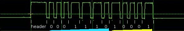
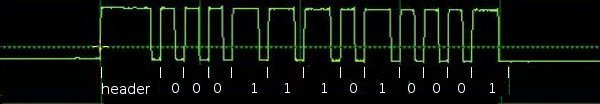
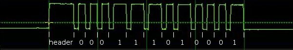
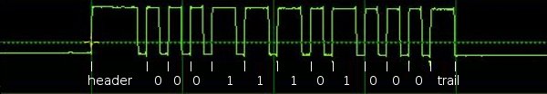
I've extended my Arduino IRremote library to support RC6 codes up to 64 bits long. Now your Arduino can control your Xbox by acting as an IR remote control. (The previous version of my library only supported 32 bit codes, so it didn't work with the 36-bit Xbox codes.) Details of the IRremote library are here.

Note: I don't actually have an Xbox to test this code with, so please let me know if the code works for you.

Download

This code is in my "experimental" branch since I'd like to get some testing before releasing it to the world. To use it:
  • Download the IRremote library zip file from GitHub from the Arduino-IRremote experimental branch.
  • Unzip the download
  • Move/rename the shirriff-Arduino-IRremote-nnnn directory to arduino-000nn/libraries/IRremote.

Sending an Xbox code

The following program simply turns the Xbox on, waits 10 seconds, turns it off, and repeats.
#include <IRremote.h>
IRsend irsend;
unsigned long long OnOff = 0xc800f740cLL;
int toggle = 0;

void sendOnOff() {
  if (toggle == 0) {
    irsend.sendRC6(OnOff, 36);
  } else {
    irsend.sendRC6(OnOff ^ 0x8000, 36);
  }
  toggle = 1 - toggle;
}
   
void setup() {}

void loop() {
  delay(10000);  // Wait 10 seconds
  sendOnOff();  // Send power signal
}
The first important thing to note is that the On/Off code is "unsigned long long", and the associated constant ends in "LL" to indicate that it is a long long. Because a regular long is only 32 bits, a 64-bit long long must be used to hold the 64 bit code. If you try using a regular long, you'll lose the top 4 bits ("C") from the code.

The second thing to notice is the toggle bit (which is explained in more detail below). Every time you send a RC5 or RC6 code, you must flip the toggle bit. Otherwise the receiver will ignore the code. If you want to send the code multiple times for reliability, don't flip the toggle bit until you're done.

Receiving an Xbox code

The following code will print a message on the serial console if it receives an Xbox power code. It will also dump the received value.
#include <IRremote.h>

int RECV_PIN = 11;
IRrecv irrecv(RECV_PIN);
decode_results results;

void setup()
{
  Serial.begin(9600);
  irrecv.enableIRIn(); // Start the receiver
}

void loop() {
  if (irrecv.decode(&results)) {
    if ((results.value & ~0x8000LL) == 0xc800f740cLL) {
      Serial.println("Got an OnOff code");
    }
    Serial.println(results.value >> 32, HEX);
    Serial.println(results.value, HEX);
    irrecv.resume(); // Receive the next value
  }
}
Two things to note in the above code. First, the received value is anded with ~0x8000LL; this clears out the toggle bit. Second, Serial.println is called twice, first to print the top 32 bits, and second to print the bottom 32 bits.

The output when sent power codes multiple times is:

Got an OnOff code
C
800FF40C
Got an OnOff code
C
800F740C
Got an OnOff code
C
...
Note that the received value is split between the two Serial.println calls. Also note that the output oscillates between ...F740C and ...FF40C as the sender flips the toggle bit. This is why the toggle bit must be cleared when looking for a particular value.

The IRremote/IRrecvDump example code has also been extended to display values up to 64 bits, and can be used for testing.

A quick description of RC6 codes

RC6 codes are somewhat more complicated than the usual IR code. They come in 20 or 36 bit varieties (that I know of). The code consists of a leader pulse, a start bit, and then the 20 (or 36) data bits. A 0 bit is sent as a space (off) followed by a mark (on), while a 1 bit is sent as a mark (on) followed by a space (off).

The first complication is the fourth data bit sent (called a trailer bit for some reason), is twice as long as the rest of the bits. The IRremote library handles this transparently.

The second complication is RC5 and RC6 codes use a "toggle bit" to distinguish between a button that is held down and a button that is pressed twice. While a button is held down, a code is sent. When the button is released and pressed a second time, a new code with one bit flipped is sent. On the third press, the original code is sent. When sending with the IRremote library, you must keep track of the toggle bit and flip it each time you send. When receiving with the IRremote library, you will receive one of two different codes, so you must clear out the toggle bit. (I would like the library to handle this transparently, but I haven't figured out a good way to do it.)

For details of the RC6 encoding with diagrams and timings, see SB projects.

The LIRC database

The LIRC project collects IR codes for many different remotes. If you want to use RC6 codes from LIRC, there a few things to know. A typical code is the Xbox360 file, excerpted below:
begin remote
  name  Microsoft_Xbox360
  bits           16
  flags RC6|CONST_LENGTH
  pre_data_bits   21
  pre_data       0x37FF0
  toggle_bit_mask 0x8000
  rc6_mask    0x100000000

      begin codes
          OpenClose                0x8BD7
          XboxFancyButton          0x0B9B
          OnOff                    0x8BF3
...
To use these RC6 code with the Arduino takes a bit of work. First, the codes have been split into 21 bits of pre-data, followed by 16 bits of data. So if you want the OnOff code, you need to concatenate the bits together, to get 37 bits: 0x37ff08bf3. The second factor is the Arduino library provides the first start bit automatically, so you only need to use 36 bits. The third issue is the LIRC files inconveniently have 0 and 1 bits swapped, so you'll need to invert the code. The result is the 36-bit code 0xc800f740c that can be used with the IRremote library.

The rc6_mask specifies which bit is the double-wide "trailer" bit, which is the fourth bit sent (both in 20 and 36 bit RC6 codes). The library handles this bit automatically, so you can ignore it.

The toggle_bit_mask is important, as it indicates which position needs to be toggled every other transmission. For example, to transmit OnOff you will send 0xc800f740c the first time, but the next time you will need to transmit 0xc800ff40c.

More details of the LIRC config file format are at WinLIRC.

Xbox codes

Based on the LIRC file, the following Xbox codes should work with my library:
OpenClose0xc800f7428XboxFancyButton0xc800ff464OnOff0xc800f740c
Stop0xc800ff419Pause0xc800f7418Rewind0xc800ff415
FastForward0xc800f7414Prev0xc800ff41bNext0xc800f741a
Play0xc800ff416Display0xc800f744fTitle0xc800ff451
DVD_Menu0xc800f7424Back0xc800ff423Info0xc800f740f
UpArrow0xc800ff41eLeftArrow0xc800f7420RightArrow0xc800ff421
DownArrow0xc800f741fOK0xc800ff422Y0xc800f7426
X0xc800ff468A0xc800f7466B0xc800ff425
ChUp0xc800f7412ChDown0xc800ff413VolDown0xc800ff411
VolUp0xc800ff410Mute0xc800ff40eStart0xc800ff40d
Play0xc800f7416Enter0xc800ff40bRecord0xc800f7417
Clear0xc800ff40a00xc800f740010xc800f7401
20xc800ff40230xc800f740340xc800ff404
50xc800f740560xc800ff40670xc800f7407
80xc800ff40890xc800f74091000xc800ff41d
Reload0xc800f741c

Key points for debugging

The following are the main things to remember when dealing with 36-bit RC6 codes:
  • Any 36-bit hex values must start with "0x" and end with "LL". If you get the error "integer constant is too large for 'long' type", you probably forgot the LL.
  • You must use "long long" or "unsigned long long" to hold 36-bit values.
  • Serial.print will not properly print 36-bit values; it will only print the lower 32 bits.
  • You must flip the toggle bit every other time when you send a RC6 code, or the receiver will ignore your code.
  • You will receive two different values for each button depending if the sender has flipped the toggle bit or not.

Control your mouse with an IR remote

You can use an IR remote to control your computer's keyboard and mouse by using my Arduino IR remote library and a small microcontroller board called the Teensy. By pushing the buttons on your IR remote, you can steer the cursor around the screen, click on things, and enter digits. The key is the Teensy can simulate a USB keyboard and mouse, and provide input to your computer.

How to do this

I built a simple sketch that uses the remote from my DVD player to move and click the mouse, enter digits, or page up or down. Follow these steps:
  • The hardware is nearly trivial. Connect a IR detector to the Teensy: detector pin 1 to Teensy input 11, detector pin 2 to ground, and detector pin 3 to +5 volts.
  • Install the latest version of my IR remote library, which has support for the Teensy.
  • Download the IRusb sketch.
  • In the Arduino IDE, select Tools > Board: Teensy 2.0 and select Tools > USB Type: Keyboard and Mouse.
  • Modify the sketch to match the codes from your remote. Look at the serial console as you push the buttons on your remote, and modify the sketch accordingly. (This is explained in more detail below.)
To reiterate, this sketch won't work on a standard Arduino; you need to use a Teensy.

How the sketch works

The software is straightforward because the Teensy has USB support built in. First, the IR library is initialized to receive IR codes on pin 11:
#include <IRremote.h>

int RECV_PIN = 11;
IRrecv irrecv(RECV_PIN);
decode_results results;

void setup()
{
  irrecv.enableIRIn(); // Start the receiver
  Serial.begin(9600);
}
Next, the decode method is called to receive IR codes. If the hex value for the received code corresponds to a desired button, a USB mouse or keyboard command is sent. If a code is not recognized, it is printed on the serial port. Finally, after receiving a code, the resume method is called to resume receiving IR codes.
int step = 1;
void loop() {
  if (irrecv.decode(&results)) {
    switch (results.value) {
    case 0x9eb92: // Sony up
      Mouse.move(0, -step); // up
      break;
    case 0x5eb92:  // Sony down
      Mouse.move(0, step); // down
      break;
...
    case 0x90b92:  // Sony 0
      Keyboard.print("0");
      break;
...
    default:
      Serial.print("Received 0x");
      Serial.println(results.value, HEX);
      break;
    }
    irrecv.resume(); // Resume decoding (necessary!)
  }
}
You may wonder where the codes such as 0x9eb92 come from. These values are for my Sony DVD remote, so chances are they won't work for your remote. To get the values for your remote, look at the serial console as you press the desired buttons. As long as you have a supported remote type (NEC, Sony, RC5/6), you'll get the hex values to put into the sketch. Simply copy the hex values into the sketch, and perform the desired action.

There are a few details to note. If your remote uses the RC5 or RC6 format, there are actually two different codes assigned to each button, and the remote alternates between them. Push the button twice to see if you'll need to use two different codes. If you want to send a non-ASCII keyboard code, such as Page Down, you'll need to use a slightly more complex set of commands (documentation). For example, the following code sends a Page UP if it receives a RC5 Volume Up from the remote. Note that there are two codes for volume up, and note that KEY_PAGE_UP is sent, followed by 0 (no key).

    case 0x10: // RC5 vol up
    case 0x810:
      Keyboard.set_key1(KEY_PAGE_UP);
      Keyboard.send_now();
      Keyboard.set_key1(0);
      Keyboard.send_now();
      break;

Improvements

My first implementation of the sketch as described above was very easy, but there were a couple displeasing things. The first problem was the mouse movement was either very slow (with a small step size) or too jerky (with a large step size). Second, if you press a number on the remote, the keyboard input rapidly repeats because the IR remote repeatedly sends the IR code, so you end up with "111111" when you just wanted "1".

The solution to the mouse movement is to implement acceleration - as you hold the button down, the mouse moves faster. This was straightforward to implement. The sketch checks if the button code was received within 200ms of the previous code. If so, the sketch speeds up the mouse movement by increasing the step size. Otherwise it resets the step size to 1. The result is that tapping the button gives you fine control by moving the mouse a little bit, while holding the button down lets you zip across the screen:

    if (millis() - lastTime > GAP) {
      step = 1;
    } 
    else if (step > 20) {
      step += 1;
    }
Similarly, to prevent the keyboard action from repeating, we only output keypresses if the press is more then 200ms after the previous. This results in a single keyboard action no matter how long a button is pressed down. The same thing is done to prevent multiple mouse clicks.
 if (millis() - lastTime > GAP) {
        switch (results.value) {
        case 0xd0b92:
          Mouse.click();
          break;
        case 0x90b92:
          Keyboard.print("0");
          break;
...

Now you can control your PC from across the room by using your remote. Thanks to Paul Stoffregen of PJRC for porting my IR remote library to the Teensy and sending me a Teensy for testing.

IRremote library now runs on the Teensy, Arduino Mega, and Sanguino

Thanks to Paul Stoffregen of PJRC, my Arduino IR remote library now runs on a bunch of different platforms, including the Teensy, Arduino Mega, and Sanguino. Paul has details here, along with documentation on the library that I admit is better than mine.

I used my new IRremote test setup to verify that the library works fine on the Teensy. I haven't tested my library on the other platforms because I don't have the hardware so let me know if you have success or run into problems.

Download

The latest version of the IRremote library with the multi-platform improvements is on GitHub. To download and install the library:
  • Download the IRremote library zip file from GitHub.
  • Unzip the download
  • Move/rename the shirriff-Arduino-IRremote-nnnn directory to arduino-000nn/libraries/IRremote.

Thanks again to Paul for adding this major improvement to my library and sending me a Teensy to test it out. You can see from the picture that the Teensy provides functionality similar to the Arduino in a much smaller package that is also breadboard-compatible; I give it a thumbs-up.

Testing the Arduino IR remote library

I wrote an IR remote library for the Arduino (details) that has turned out to be popular. I want to make sure I don't break things as I improve the library, so I've created a test suite that uses a pair of Arduinos: one sends data and the other receives data. The receiver verifies the data, providing an end-to-end test that the library is working properly.

Overview of the test

The first Arudino repeatedly sends a bunch of IR codes to the second Arduino. The second Arduino verifies that the received code is what is expected. If all is well, the second Arduino flashes the LED for each successful code. If there is an error, the second Arudino's LED illuminates for 5 seconds. The test cycle repeats forever. Debugging information is output to the second Arduino's serial port, which is helpful for tracking down the cause of errors.

Hardware setup

The test hardware is pretty simple: one Arduino transmits, and one Arduino receives. An IR LED is connected to pin 3 of the first Arduino to send the IR code. An IR detector is connected to pin 11 of the second Arduino to receive the IR code. A LED is connected to pin 3 of the second Arduino to provide the test status.
schematic of test setup

Details of the test software

One interesting feature of this test is the same sketch runs on the sending Arduino and the receiving Arduino. The test looks for an input on pin 11 to decide if it is the receiver:
void setup()
{
  Serial.begin(9600);
  // Check RECV_PIN to decide if we're RECEIVER or SENDER
  if (digitalRead(RECV_PIN) == HIGH) {
    mode = RECEIVER;
    irrecv.enableIRIn();
    pinMode(LED_PIN, OUTPUT);
    digitalWrite(LED_PIN, LOW);
    Serial.println("Receiver mode");
  } 
  else {
    mode = SENDER;
    Serial.println("Sender mode");
  }
}
Another interesting feature is the test suite is expressed very simply:
  test("SONY4", SONY, 0x12345, 20);
  test("SONY5", SONY, 0x00000, 20);
  test("SONY6", SONY, 0xfffff, 20);
  test("NEC1", NEC, 0x12345678, 32);
  test("NEC2", NEC, 0x00000000, 32);
  test("NEC3", NEC, 0xffffffff, 32);
...
Each test call has a debugging string, the type of code to send/receive, the value to send/receive, and the number of bits.

On the sender, the testmethod sends the code, while on the receiver, the method verifies that the proper code is received. The SENDER code calls the appropriate send method based on the type, and then delays before the next test. The RECEIVER code waits for a code. If it's correct, it flashes the LED. Otherwise, it sets the state to ERROR.

void test(char *label, int type, unsigned long value, int bits) {
  if (mode == SENDER) {
    Serial.println(label);
    if (type == NEC) {
      irsend.sendNEC(value, bits);
    } 
    else if (type == SONY) {
...
    }
    delay(200);
  } 
  else if (mode == RECEIVER) {
    irrecv.resume(); // Receive the next value
    unsigned long max_time = millis() + 30000;
    // Wait for decode or timeout
    while (!irrecv.decode(&results)) {
      if (millis() > max_time) {
        mode = ERROR; // timeout
        return;
      }
    }
    if (type == results.decode_type && value == results.value && bits == results.bits) {
      // flash LED
    } 
    else {
      mode = ERROR;
    }
  }
}
The trickiest part of the code is synchronizing the sender and the receiver. This happens in loop(). The receiver waits for 1 second without any transmission, while the sender pauses for 2 seconds after each time through the tests. Thus, the receiver will wait while the sender is running through tests, and then will start listening just before the sender starts the next cycle of tests. One other thing to point out is if there is an error, the receiver will skip through all the remaining tests, light the LED to indicate the error, and then will wait to sync up again. This avoids the problem of one bad test getting the receiver permanently out of sync; the receiver is able to re-sync and continue successfully after a failed test.
void loop() {
  if (mode == SENDER) {
    delay(2000);  // Delay for more than gap to give receiver a better chance to sync.
  } 
  else if (mode == RECEIVER) {
    waitForGap(1000);
  } 
  else if (mode == ERROR) {
    // Light up for 5 seconds for error
    mode = RECEIVER;  // Try again
    return;
  }
The test also includes some raw mode tests. These are a bit more complicated, since I want to test the various combinations of sending and receiving in raw mode.

Download and running

I'm gradually moving my development to GitHub at https://github.com/shirriff/Arduino-IRremote.

The code fragments above have been slightly abbreviated; the full code for the test sketch is here.

To download the library and try out the two-Arduino test:

  • Download the IRremote library zip file.
  • Unzip the download
  • Move/rename the shirriff-Arduino-IRremote-nnnn directory to arduino-000nn/libraries/IRremote. The test sketch is in examples/IRtest2.

To run the test, install the sketch on two Arduinos. The test should automatically start running. Note that it is a bit tricky to use two Arduinos at once. They will probably get assigned different serial ports, and you can switch ports using the Tools menu. If you get confused, you can plug one Arduino in at a time, and then you can be sure about which one is getting installed.

My plan is to do more development on the library, now that I have a reasonably solid test suite and I can be more confident that I don't break things. Let me know if there are specific features you'd like.

Thanks go to SparkFun for giving me the second Arduino that made this test possible.

Improved Arduino TV-B-Gone

Oct 2016: An updated version of the code is on github, thanks to Gabriel Staples.

The TV-B-Gone is a tiny infrared remote that can turn off almost any TV. A while ago, I ported the TV-B-Gone software to the Arduino; for details on the port and how it works see my previous post on the Arduino TV-B-Gone.

Mitch Altman, the inventor of the TV-B-Gone, made some improvements to the code for a weekly TV-B-Gone constructing workshop in San Francisco at Noisebridge. If you're in the San Francisco area and are interested in the TV-B-Gone, you might want to check it out.

The main bug fix in the new version is the European codes will now work (if you ground pin 5). (The problem was a bunch of #ifdefs to fit the codes into the ATtiny's limited memory; taking out the #ifdefs fixed the problems.) Pressing the trigger button during transmission will now restart the codes. The delay between codes was increased, which should make transmission more reliable. The Arduino's processor will now sleep when not transmitting (thanks to ka1kjz). (Unfortunately, the rest of the Arduino components are still draining power, so sleep mode will be more useful with stripped-down Arduino variants.)

Important: the pins have been changed around in the new version (to avoid conflicts with the serial port). Pin 2 is now the trigger switch, Pin 3 is the IR output, and Pin 5 is grounded if you want European codes. If you built an Arduino TV-B-Gone before and want to use the new code, make sure you connect to the right pins.

Here's Mitch Altman's schematic for the Arduino TV-B-Gone (click for larger): Arduino TV-B-Gone schematic

To build the Arduino TV-B-Gone, follow the above schematic and download the sketch from github. My previous post on the Arduino TV-B-Gone has more information on wiring it up, if you need it.

Getting the (literal) bugs out of a driveway gate controller

My driveway has a gate that automatically opens when you drive up, and then closes. Recently it stopped working and this blog post describes how I got the bugs out of the controller, reverse-engineered it, and got it working again.

The gate is controlled by a Stanley 24600 gate controller, which has the fairly simple task of running the motors to open the gate and close the gate as appropriate. Everything worked fine for years, until one recent day it just stopped working, which was rather inconvenient. When I opened up the controller box, I noticed a couple potential problems.
Gate controller box infested with ants
First, the circuit board had some disgusting cocoons on it, which were apparently shorting out the board and preventing it from working. I don't know what sort of insect made the cocoons, and I didn't want to wait around to find out.
Gate controller board infested with cocoons
In addition, see those light brown piles at the bottom of the controller box? An ant nest had decided to move in for some reason, and they had brought thousands of eggs with them. I don't think the ants were actually interfering with the function of the controller, but it's hard to debug a circuit when ants keep crawling on you. Here's a closeup of the pile of eggs:
Closeup of ants and eggs in the controller.
Getting rid of the ant nest was easy. Opening up the box scared the ants, and they scurried around and moved out in 15 minutes flat, taking the eggs with them. I replaced the weather stripping around the box to keep them out.

The hideous cocoons on the other hand were a bigger problem. I removed them from the board and scrubbed the circuit board clean with rubbing alcohol. After replacing the circuit board, the gate would start opening but would not stop opening, which was a change but not really an improvement.

Everything else checked out fine (power, fuses, sensors, motors), so I knew the problem had to be in the controller. Unfortunately the controller is obsolete and nobody makes replacements or has documentation, so I figured I better get it fixed. I started poking around the circuit boards to try to figure out how they worked and where the problem might be.

The logic provided by the controller is simple, but not trivial: it can use a signal to open, or can use a signal to both open and close, or can use a signal to reverse, and has a stop signal. It also has a separate board to automatically close after a delay.

The controller is implemented using some CMOS gates and flip flops for the logic, and a couple 555 timers to control how long to run the motors to open and close the gates. Three big relays and two giant capacitors control the motors, while a few small relays provide additional logic. The controller also has a handful of transistors for various functions, and a bunch of resistors, diodes, and capacitors. The board on the right is the main logic board, and the smaller board on the left provides the optional automatic-close function. Note the variable resistors (with long white shafts) to adjust the various timings. There's also an AC-to-DC circuit on the board to power the logic, and a triac to switch low-voltage AC on and off for reasons I never figured out.

Newer controllers, of course, replace all this discrete logic with a microcontroller. They also provide a lot more functionality and options. It's interesting, though, to see how these circuits were implemented in the "olden days".
Gate controller circuit boards

I spent a bunch of time following PCB traces around (both visually and with a continuity tester) trying to figure out how all the pieces work together. It was a slower process than I had expected, since many of the traces go under components and you can't see where they end up. I was getting frustrated and considered building my own controller out of an Arduino, since it would be about 10 lines of code. However, I figured interfacing with the sensors and AC relays would be a pain, and I didn't want to burn out the expensive motors with a programming error. Thus, I continued to analyze the existing controller.

I got most of the logic figured out when I happened to discover a trace that didn't have continuity from one end to the other. Apparently one of the traces that powers some of the transistors had cracked while I was cleaning off the cocoons. I put a jumper across the bad trace, and everything worked perfectly:
Jumper wire to fix controller board

I've had lots of computer problems due to bugs, but this is the first time my problem was real live insect bugs. (Obligatory Grace Hopper bug link.)

Update: Nature still hates my gate

Today, my gate would only close half-way. After some investigation, I discovered that a vine had somehow gotten caught on the gate, and it was strong enough to keep the gate from closing all the way. I was a bit surprised that the gate motors weren't strong enough to rip the vine off, but I guess as a safety feature they don't have a lot of extra force. This problem was a lot easier to fix than the previous, since I just needed to remove the vine.

I conclude, however, that nature hates my gate and is trying to keep it from working, whether it takes insects or plants. What next? Ice storm? Tornado?
A vine attacks my gate

Understanding Sony IR remote codes, LIRC files, and the Arduino library

This article describes how to understand Sony IR codes and how to get them from the LIRC files. The article is intended to describe codes for use with my Arduino infrared remote library, but the information should be generally applicable. This article is aimed at the hardware hacker and assumes that you are familiar with binary and hexadecimal, so be warned :-)

One key point of this article is that there are three different ways to interpret the same IR signal and turn it into a hex code. Understanding these three ways will allow you to get codes from different sources and understand them correctly.

The IR transmission of the code

When you press a button on a Sony remote control, an infrared signal is transmitted. This transmission consists of a 40kHz signal which is turned on and off in a particular pattern. Different buttons correspond to different codes, which cause the signal to be turned on and off in different patterns.

The following waveform shows the IR code transmitted for STOP on my Sony CD remote control (RM-DC335). When the signal is high, a 40 kHz IR signal is transmitted, and when the signal is low, nothing is transmitted. In other words, the signal is actually rapidly turning on and off when it appears to be on in the figure. (The IR receiver demodulated the signal, so you don't see the 40 kHz transitions.)
IR transmission for a Sony remote control
A Sony IR signal starts with 2400 microseconds on and 600 microseconds off; that's the first wide pulse. A "1" bit is transmitted with 1200 microseconds on and 600 microseconds off, while a "0" bit is transmitted with 600 microseconds on and 600 microseconds off. (This encoding is also called SIRC or SIRCS encoding.)

You may notice the "on" parts of the waveform appear wider than the "off" parts, even when both are supposed to be 600 microseconds. This is a result of the IR receiver, which switches on faster than switching off.

The above waveform represents one transmission of a 12-bit code. This transmission is normally repeated as long as the button is held down, and a minimum of three times. Each transmission starts 45ms after the previous one started. The Sony protocol also supports 15 and 20 bit codes, which are the same as above except with more bits.

For more information on the low-level transmission of Sony codes, see sbprojects.net.

Three ways to interpret the codes

The Sony encoding seems straightforward, but there are several different ways the signal can be interpreted. I will call these official decoding, bit decoding, and bit-1 decoding. Different sources use any of these three, which can cause confusion. I will explain these three decodings, using the previous waveform as an example.

Official decoding

Official Sony decoding
The "official" Sony protocol views the 12-bit code as 7 command bits and 5 address or device bits, transmitted least-significant-bit first (i.e. "backwards"). The device bits specify the type of device receiving the code, and the command bits specify a particular command for this device. In this example, the device bits (yellow) are 10001 when read right-to-left, which is 17 decimal. The command bits (blue) are 0111000 when read right-to-left, which is 56 decimal. The device value 17 corresponds to a CD player, and the command 56 corresponds to the STOP command (details).

Sony 15 bit codes are similar, with 7 command bits and 8 device bits. Sony 20 bit codes have 7 command bits, 5 device bits, and 8 extended device bits.

Bit decoding

Decoding Sony IR code as a sequence of bits
Many IR decoders just treat the signal as a sequence of bits, most-significant-bit first. I will call this bit decoding. Applying this interpretation to the above code, the code is interpreted as 0001 1101 0001 binary, or 1d1 hex, or 465 in decimal. Note that the last bit doesn't really consist of 1200 microseonds on and 600 microseconds off; it consists of 1200 microseconds on followed by a lot of time off. In other words, the transmission is off for 600 microseconds and then continues to be off until the next code is transmitted.

An alternative but equivalent interpretation is to view the code as a 2400 microsecond header, followed by 12 bits, where each bit is off then on (rather than on then off). A "1" bit is 600 microseconds off and 1200 microseconds on, while a "0" bit is 600 microseconds off and 600 microseconds on. This yields the same value as before (232 decimal), but avoids the special handling of the last bit.
Short one bit decoding

Bit-1 decoding

Short one bit decoding
Many IR decoders drop the last bit, which I will call bit-1 decoding. Because the last bit doesn't end nicely with 600 microseconds off, some IR decoding algorithms treat the signal as 11 bits of data, ending with 600 microseconds on as a trailer. In this interpretation, the above code is 000 1110 1000 binary, or 0e8 hex, or 232 decimal. (Note that doubling this value and adding 1 yields the previous decoding of 465.)

Discussion

Is the code really 17/44 or 465 or 232? The official decoding is "right" in the sense that it is what the manufacturer intends. In addition, it reveals the internal structure of the code and the codes make more sense. For instance, the buttons 1-9 have consecutive codes with the official decoding, but not with the others. The other decodings are fine to use as long as you're consistent; the main thing is to understand that different sources use different decodings. My Arduino library uses the second bit decoding interpretation. The different decodings can be converted from one form to another with binary arithmetic.

Getting codes from a remote

Probably the easiest way to get the codes for your device is to use your existing remote control and see what codes it transmits. You can use my Arduino IR library to do the decoding, with the IRrecvDump demo program. Take a 3-pin IR decoder, hook it up to an Arduino, and then you can read the values for each button press on the serial port.

Alternatively, you can look at the transmitted codes with an oscilloscope. For the diagrams above, I used an IR receiver module connected to two resistors (to drop the voltage), connected to the line input of my PC. I used the Zeitnitz Soundcard Oscilloscope program to display the signal. This lets you see exactly what is being transmitted, but you will need to stare at the screen, write down a bunch of 0's and 1's, and convert the binary value to get your codes.

Getting codes from LIRC files

The best source for IR codes that I've found is the Linux Infrared Remote Control project (lirc.org), which has a huge collection of config files for various remotes. (LIRC also includes a large collection of device drivers for many types of IR input/output hardware, and a software library.)

The LIRC config file format is documented at WinLIRC, but I will walk through some examples.

Bit decoding

The RM-S530 LIRC file treats the codes as 12 bits long, using what I call bit decoding:
begin remote

  name  Sony
  bits           12
  flags SPACE_ENC|CONST_LENGTH
  eps            30
  aeps          100

  header       2470   557
  one          1243   556
  zero          644   556
  gap          45076
  min_repeat      2
  toggle_bit      0


      begin codes
          sleep                    0x0000000000000061
          cd_stop                  0x00000000000001D1
...
This file indicates that each entry is 12 bits long. A header consists of on for 2470 microseconds and off for 557 microseconds. A one bit consists of on for 1243 microseconds and off for 556 microseconds. A zero bit consists of on for 644 microseconds and off for 556 microseconds. Codes are repeated a minimum of 2 more times, with a gap of 45076 microseconds from start to start as the codes are constant length (CONST_LENGTH).

You may be wondering why these time values don't match the official values of 2400, 1200, and 600 microseconds. First, the LIRC data is generally measured from actual remotes, so the real-world timings don't quite match the theory. Second, IR sensors have some lag in detecting "on" and "off", and they typically stretch out the "on" time by ~100 microseconds, shortening the "off" time equally.

The LIRC file then lists the hex code associated with each button. For example the CD STOP code is hex 1D1, which is the same value as described earlier.

Bit-1 decoding

The LIRC file for the RM-D302 remote treats the codes as 11 bits and a trailing pulse. This is what I call the bit-1 decoding:
begin remote

  name  RM-D302
  bits           11
  flags SPACE_ENC|CONST_LENGTH
  eps            30
  aeps          100

  header       2367   638
  one          1166   637
  zero          565   637
  ptrail       1166
  gap          45101
  min_repeat      2
  toggle_bit      0


      begin codes
          cd_stop                  0x00000000000000E8
The key differences with the previous file are the ptrail field, indicating a trailing pulse of 1166 microseconds; and the bit count of 11 instead of 12. Note that the code value is different from the first file, even thought the IR transmission is exactly the same. The hex code 0E8 is the same as described earlier under bit-1 decoding.

Pre_data and post_data bits

Some LIRC files break apart the codes into constant pre_data bits, the code itself, and constant post_data bits. For instance, the file for my RM-D335 remote:
begin remote

  name  SONY
  bits            7
  flags SPACE_ENC
  eps            20
  aeps            0

  header       2563   520
  one          1274   520
  zero          671   520
  ptrail       1274
  post_data_bits  4
  post_data      0x8
  gap          25040
  min_repeat      2

      begin codes
          CONTINUE                 0x000000000000005C
...
          STOP                     0x000000000000000E
...
This file indicates that each code entry is 7 bits long, but there are also 4 post data bits. This means that after transmitting the 7 bits for the code, 4 additional bits are transmitted with the "post data" hex value 0x8, i.e. 1000 binary.

Putting this together the STOP button has the hex value 0E, which corresponds to the seven bits 000 1110. This is followed by four post data bits 1000, so the total transmission is the eleven bits 000 1110 1000, which is 0E8 hex, the same as before for the bit-1 decoding.

One more thing to notice in this LIRC file is it doesn't have the CONST_LENGTH flag, and the gap is 25ms instead of 45ms. This indicates the gap is from the end of one code to the start of the next, rather than from the start of one code to the start of the next. Specifying a gap between codes isn't how Sony codes are actually defined, it's close enough.

LIRC summary

Note that these LIRC files all indicate exactly the same IR transmission; they just interpret it differently. The first file defines the STOP code as 1D1, the second as E8, and the third as 0E.

What does this mean to you? If you want to get a Sony code from a LIRC file and use it with the Arduino library, you need to have a 12 bit (or 15 or 20 bit) code to pass to the library (bit decoding). Look up the code in the file and extract the specified number of bits. If there are any pre_data or post_data bits, append them as appropriate. If the result is one bit short and the LIRC file has a ptrail value, append a 1 bit on the end to convert from bit-1 decoding to bit decoding. Convert the result to hex and you should have the proper code for your device, that can be used with the Arduino library.

Getting codes from hifi-remote.com

The most detailed site I've found on Sony codes specifically is hifi-remote.com/sony. An interesting thing about this site is it analyzes the structure of the codes. While the LIRC files just list the codes, the hifi-remote site tries to explain why the codes are set up the way they are.

Note that this site expresses codes in Sony format, i.e. most-significant-bit first, and separating the device part of the code from the command part of the code. Also for a 20-bit Sony code, the 13 bit device code is expressed as a 5 bit value and an 8 bit value separated by a period. As a result, you may need to do some binary conversion and reverse the bits to use these codes.

To work through an example, I can look up the data for a Sony CD. There are multiple device codes, but assume for now I know my device code is 17. The table gives the code 56 for STOP. Convert 56 to the 7 bit binary value 0111000 and reverse it to get 0001110. Convert 17 to the 5 bit binary value 10001 and reverse it to get 10001. Put these together to et 000111010001, which is 1D1 hex, as before.

To work through a 20-bit example, if I have a Sony VCR/DVD Combo with a device code of 26.83, the site tells me that the code for "power" is 21. Convert 21 to a 7 bit binary value, 26 to a 5 bit binary value, and 83 to a 8 bit binary value. Then reverse and concatenate the bits: binary 1010100 + 01011 + 11001010, which is a8bca in hex. To confirm, the RMT-V501A LIRC file lists power as A8B with post_data of CA.

To use this site, you pretty much have to know the device code for your device already. To find that, obtain a code for your device (e.g. from your existing remote or from LIRC), split out and reverse the appropriate bits, and look up the device code on the site. Alternatively, there are only a few different device codes for a particular type of device, so you can just try them all and see what works.

This site also has information on "discrete codes". To understand discrete codes, consider the power button on a remote that toggles between "on" and "off". This may be inconvenient for automated control, since without knowing the current state, you don't know if sending a code will turn the device on or off. The solution is the "discrete code", which provides separate "on" and "off" codes. Discrete codes may also be provided for operations such as selecting an input or mode. Since these codes aren't on the remote, they are difficult to obtain.

Other sites

Additional config files are available at irremote.psiloc.com. These are in LIRC format, but translated to XML. The site remotecentral.com has a ton of information on remotes, but mostly expressed in proprietary formats.

Conclusion

Hopefully this will clear up some of the confusion around Sony remote codes, without adding additional confusion :-)