Showing posts sorted by relevance for query ir. Sort by date Show all posts

An Arduino universal remote: record and playback IR signals

I've implemented a simple IR universal remote that will record an IR code and retransmit it on demand as an example for my IR library. Handling IR codes is a bit more complex than it might seem, as many protocols require more than simply recording and playing back the signal.

To use the universal remote, simply point your remote control at the IR module and press a button on the remote control. Then press the Arduino button whenever you want to retransmit the code. My example only supports a single code at a time, but can be easily extended to support multiple codes.

The hardware

The IR recorder
The above picture shows the 9V battery pack, the Arduino board, and the proto board with (top-to-bottom) the IR LED, IR receiver, and pushbutton.

The circuitry is simple: an IR sensor module is connected to pin 11 to record the code, an IR LED is connected to pin 3 to transmit the code, and a control button is connected to pin 12. (My IR library article has details on the sensor and LED if you need them.)
Schematic of the IR recorder

The software

The code can be downloaded as part of my IRremote library download; it is the IRrecord example.

Handling different protocols

The code supports multiple IR protocols, each with its own slight complications:

Sony codes can be recorded and played back directly. The button must be held down long enough to transmit a couple times, as Sony devices typically require more than one transmission.

The common NEC protocol is complicated by its "repeat code". If you hold down a button, the remote transmits the code once followed by multiple transmissions of special repeat code. The universal remote records the code, not the repeat code. On playback, it transmits the code once, followed by the repeat code.

The RC5 and RC6 protocols handle repeated transmissions differently. They use two separate codes for each function, differing in a "toggle bit". The first time you hold down a button, the first code is transmitted repeatedly. The next time you hold down a button, the second code is transmitted repeatedly. Subsequent presses continue to alternate. The universal remote code flips the toggle bit each time it transmits.

The universal remote handles any other unknown protocol as a "raw" sequence of modulated IR on and off. The main complication is that IR sensor modules typically stretch out the length of the "on time" by ~100us, and shorten the "off time" correspondingly. The code compensates for this.

Most likely there are some codes that that can't handle, but it has worked with the remotes I've tried.

The code also prints debugging information to the serial console, which can be helpful for debugging any problems.

In conclusion, this is intended as a proof of concept rather than a useful product. The main limitation is supporting one code at a time, but it's straightforward to extend the code. Also note that the record and playback functions can be separated; if you know the IR codes you're dealing with, you can use just the necessary function.

Controlling your stereo over the web with the Arduino infrared library

Here's how you can control your stereo over the web. Not only that, but any other electronics with a IR remote control can now be controlled through your browser. You can even use your smart phone's browser to control your stereo from across the room or around the world.
Remote control on G1 phone
This project has several pieces: a simple Python web server running on your computer, an Arduino with my infrared library, and an IR LED or other emitter. The Python web server provides a web page with a graphical remote control. Clicking on the web page sends a code to the web server, which sends it over the serial port to the Arduino, which sends it to the IR LED, which controls your device.

The web server

I used a rather trivial Python web server (based on SimpleHTTPServer) that performs two tasks. First, it provides the static HTML pages and images. Second, it receives the POST requests and sends them to the Arduino using the pyserial library.

The following code excerpt shows the handler that processes POSTs to /arduino by extracting the code value out of the POST data and sending it to the Arduino over the serial line. The Python server automatically provides static pages out of the current directory by default; this is how the HTML files and images are served. The code assumes the serial port is /dev/ttyUSB0, which is typically the case on Linux.

class MyHandler(SimpleHTTPRequestHandler):
  def do_POST(self):
    if self.path == '/arduino':
      form = cgi.FieldStorage(fp=self.rfile, headers=self.headers,
        environ={'REQUEST_METHOD':'POST'})
      code = form['code'].value
      arduino.write(code)
      self.send_response(200)
      self.send_header('Content-type', 'text/html')
      return
    return self.do_GET()

arduino = serial.Serial('/dev/ttyUSB0', 9600, timeout=2)
server = HTTPServer(('', 8080), MyHandler).serve_forever()
The server can be accessed locally at http://localhost:8080. You may need to mess around with your firewall and router to access it externally; this is left as an exercise for the reader. I found that using my cell phone's browser via Wi-Fi worked surprisingly well, and over the cellular network there was just a slight lag (maybe 1/3 second).

The Arduino code

The code on the Arduino is pretty simple. It reads a command from the serial port and makes the appropriate IR library call. Commands consist of a character indicating the type of code, followed by 8 hex characters. For instance, "S0000004d1" sends the code 4d1 using Sony protocol; this is "play" on my Sony CD player. "N010e03fc" sends 010e03fc using NEC protocol; this turns my Harman Kardon stereo on. The full code is here, but some highlights:
void processSerialCode() {
  if (Serial.available() < 9) return;
  char type = Serial.read();
  unsigned long code = 0;
  // Read 8 hex characters into code (omitted)
  if (type == 'N') {
    irsend.sendNEC(code, 32);
  } 
  else if (type == 'S') {
    // Send Sony code 3 times
    irsend.sendSony(code, 12);
    delay(50);
    irsend.sendSony(code, 12);
    delay(50);
    irsend.sendSony(code, 12);
  }
  // More code for RC5 and RC6
}
In more detail, the Arduino waits for 9 characters to be available on the serial port. It then parses the hex value and calls the appropriate IR library send routine. The Arduino code does some special-case stuff for the different code types. Sony codes are transmitted three times as the protocol requires. The RC5 and RC6 protocol uses a toggle bit that is flipped on each transmission. (Disclaimer: I don't have RC5/RC6 devices, so this code is untested.) If your device uses a different protocol that the library doesn't support, you're out of luck unless you add the protocol to the library. That's probably not too hard; a couple people have already implemented new protocols.
Arduino controlling stereo via IR

The web page

Most of the smarts of the system are in the web page. In my setup, I have a HK-3370 stereo, and a Sony CDP-CE335 CD player. I took a picture of the remote for each and used an HTML image map to make each button clickable. Clicking on a button uses Ajax to POST the appropriate IR code to the server.

I use Ajax to send the code to the server to avoid reloading the web page on every click. The Javascript code is verbose but straightforward. The first part of the code creates the XML request object; unfortunately different browsers use different objects. The next part of the code creates and sends the POST request. The actual data sent to the server is, for instance, "code=N12345678" to send 0x12345678 using NEC protocol.

function button(value) {
  if (window.XMLHttpRequest) {
   request = new XMLHttpRequest();
  } else if (window.ActiveXObject) {
    try {
      request = new ActiveXObject("Msxml2.XMLHTTP");
    } catch (e) {
      try {
        request = new ActiveXObject("Microsoft.XMLHTTP");
      } catch (e) {}
    }
  }
  request.open('POST', '/arduino', true);
  request.setRequestHeader('Content-type', 'application/x-www-form-urlencoded');
  request.setRequestHeader('Content-length', value.length);
  request.setRequestHeader('Connection', 'close');
  request.send('code=' + value);
}
The clickable buttons are defined in the HTML through an image and an image map. Generating the image and the image map is the hard part of the whole project:
<img src="hk3370.png" width="268" height="800" border="0" usemap="#map" />
<map name="map">
<area shape="rect" coords="60,97,85,111" href="#" alt="on" onClick="button('N010e03fc')" />
<area shape="rect" coords="104,98,129,109" href="#" alt="off" onClick="button('N010ef906')" />
...
Each line in the map defines a region of the image as a button with a particular code. When clicked, this region will call the button function with the appropriate code, causing the code to be sent to the web server, the Arduino, and finally to the stereo. The alt text isn't actually used, but I recommend it to keep track of what button is associated with each line. The href causes the cursor to change when you go over the region, but isn't necessary.
Image of remote control in Internet Explorer

In this approach, the Arduino code and web server code are very simple, as they don't need to know the functions of the codes. A different way to implement this system would be to put the table of codes ("SONY_CD_ON" = 4d1, etc.) either in the web server code or the Arduino code.

To generate the web pages, I took a picture of the remote with my camera and cleaned up the picture with GIMP. I used the GIMP image map plugin to create the image map. I outlined each button, then filled in the URL with the appropriate IR code, and filled in the alt text with the name of the button. Finally, I copied the map file into the HTML file and edited it to use the Javascript function.

The easiest way to obtain the IR codes is to use the IRrecvDump example sketch included in my IR library. Simply press the button on your remote, see what code was sent, and put that code into the image map. Alternatively, you may be able to find codes in the LIRC database.

Once you get going, it's actually fairly quick to generate the image map. Select a button in the editor, click the physical button on the remote, copy the displayed value into the editor, and move on to the next button. As long as you don't get obsessive and start tweaking the regions to line up perfectly, it's pretty quick.

If you don't want to mess around with the image map, take a look at simple.html. This file shows how to use standard HTML buttons. Not as cool as the image, but much easier:

<input type="button" value="on" onClick="button('N010e03fc')" >
<input type="button" value="off" onClick="button('N010ef906')" >
...
Simple button arrangement

The hardware

The Arduino does the work of converting the hex code into an IR signal. The IR library uses digital PWM pin 3 as output, which must be connected to your IR emitter. I use a 100 ohm resistor to limit current. Wiring it up is trivial.
Schematic of IR connection to Arduino

I used a Tivo IR blaster that I had lying around, but a plain IR LED will work too. The following picture shows an IR blaster attached to my sterero. Note that the blaster needs to be positioned about the stereo's IR receiver; it may be easier to see the receiver with a flashlight.
IR blaster attached to stereo

Putting it all together

To summarize the steps:
  • Download the files and unpack them.
  • Get the infrared library and install it.
  • Aim the IR source at the device(s) to control, and connect it to the Arduino. (You may want to use a visible LED for testing.)
  • Connect the Arduino to the computer's USB port.
  • Compile and install IRwebremote.pde using the Arduino IDE.
  • Create HTML files for your remote controls. (This is the hard step.)
  • Run the Python server: python server.py
  • Go to http://localhost:8080 and control the devices.
This project has multiple pieces and requires customization, so it's not a plug-and-play project. I only recommend trying this if you know what you're doing. Good luck!

A Multi-Protocol Infrared Remote Library for the Arduino

Code now on github

The most recent code is at github.com/shirriff/Arduino-IRremote. If you have any issues, please report them there.

Do you want to control your Arduino with an IR remote? Do you want to use your Arduino to control your stereo or other devices? This IR remote library lets you both send and receive IR remote codes in multiple protocols. It supports NEC, Sony SIRC, Philips RC5, Philips RC6, and raw protocols. If you want additional protocols, they are straightforward to add. The library can even be used to record codes from your remote and re-transmit them, as a minimal universal remote.

Arduino IR remote

To use the library, download from github and follow the installation instructions in the readme.

How to send

This infrared remote library consists of two parts: IRsend transmits IR remote packets, while IRrecv receives and decodes an IR message. IRsend uses an infrared LED connected to output pin 3. To send a message, call the send method for the desired protocol with the data to send and the number of bits to send. The examples/IRsendDemo sketch provides a simple example of how to send codes:
#include <IRremote.h>
IRsend irsend;

void setup()
{
  Serial.begin(9600);
}

void loop() {
  if (Serial.read() != -1) {
    for (int i = 0; i < 3; i++) {
      irsend.sendSony(0xa90, 12); // Sony TV power code
      delay(100);
    }
  }
} 
This sketch sends a Sony TV power on/off code whenever a character is sent to the serial port, allowing the Arduino to turn the TV on or off. (Note that Sony codes must be sent 3 times according to the protocol.)

How to receive

IRrecv uses an infrared detector connected to any digital input pin.

The examples/IRrecvDemo sketch provides a simple example of how to receive codes:

#include <IRremote.h>

int RECV_PIN = 11;
IRrecv irrecv(RECV_PIN);
decode_results results;

void setup()
{
  Serial.begin(9600);
  irrecv.enableIRIn(); // Start the receiver
}

void loop() {
  if (irrecv.decode(&results)) {
    Serial.println(results.value, HEX);
    irrecv.resume(); // Receive the next value
  }
}
The IRrecv class performs the decoding, and is initialized with enableIRIn(). The decode() method is called to see if a code has been received; if so, it returns a nonzero value and puts the results into the decode_results structure. (For details of this structure, see the examples/IRrecvDump sketch.) Once a code has been decoded, the resume() method must be called to resume receiving codes. Note that decode() does not block; the sketch can perform other operations while waiting for a code because the codes are received by an interrupt routine.
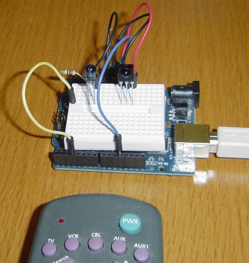
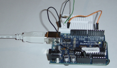
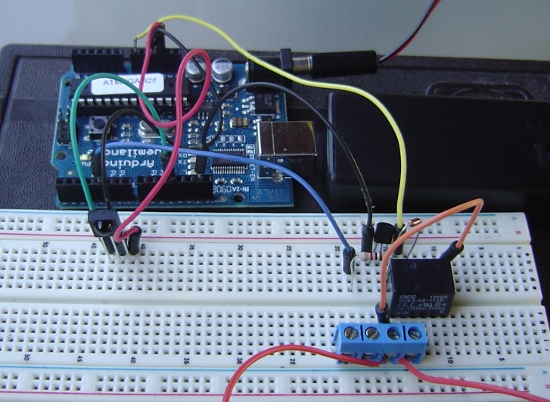
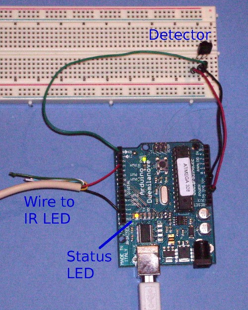
Hardware setup

The library can use any of the digital input signals to receive the input from a 38KHz IR receiver module. It has been tested with the Radio Shack 276-640 IR receiver and the Panasonic 
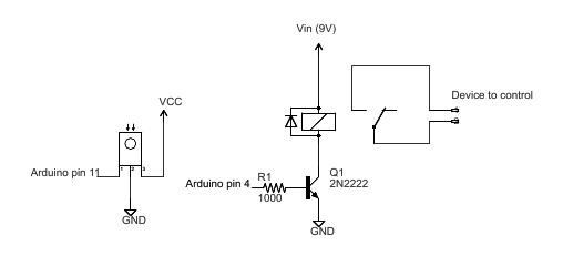
PNA4602. Simply wire power to pin 1, ground to pin 2, and the pin 3 output to an Arduino digital input pin, e.g. 11. These receivers provide a filtered and demodulated inverted logic level output; you can't just use a photodiode or phototransistor. I have found these detectors have pretty good range and easily work across a room.

IR wiring

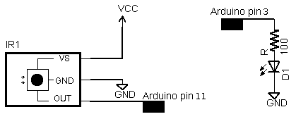
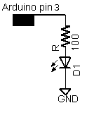
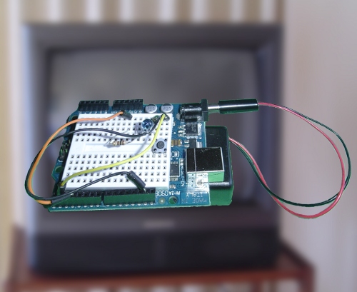
For output, connect an IR LED and appropriate resistor to PWM output pin 3. Make sure the polarity of the LED is correct, or it won't illuminate - the long lead is positive. I used a NTE 3027 LED (because that's what was handy) and 100 ohm resistor; the range is about 15 feet. For additional range, you can amplify the output with a transistor.

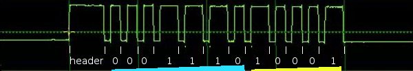
Some background on IR codes

An IR remote works by turning the LED on and off in a particular pattern. However, to prevent inteference from IR sources such as sunlight or lights, the LED is not turned on steadily, but is turned on and off at a modulation frequency (typically 36, 38, or 40KHz). The time when a modulated signal is being sent will be called a mark, and when the LED is off will be called a space.

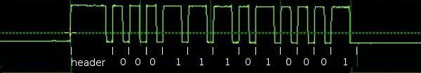
Each key on the remote has a particular code (typically 12 to 32 bits) associated with it, and broadcasts this code when the key is pressed. If the key is held down, the remote usually repeatedly broadcasts the key code. For an NEC remote, a special repeat code is sent as the key is held down, rather than repeatedly sending the code. For Philips RC5 or RC6 remotes, a bit in the code is toggled each time a key is pressed; the receiver uses this toggle bit to determine when a key is pressed down a second time.

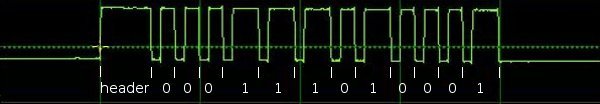
On the receiving end, the IR detector demodulates this signal, and outputs a logic-level signal indicating if it is receiving a signal or not. The IR detector will work best when its frequency matches the sender's frequency, but in practice it doesn't matter a whole lot.

The best source I've found for details on the various types of IR codes is SB IR knowledge base.

Handling raw codes

The library provides support for sending and receiving raw durations. This is intended mainly for debugging, but can also be used for protocols the library doesn't implement, or to provide universal remote functionality.

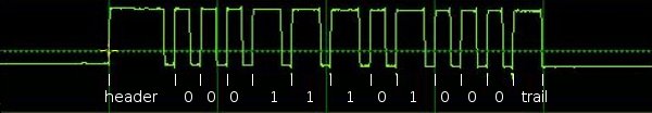
The raw data for received IR measures the duration of successive spaces and marks in 50us ticks. The first measurement is the gap, the space before the transmission starts. The last measurement is the final mark.

The raw data for sending IR holds the duration of successive marks and spaces in microseconds. The first value is the first mark, and the last value is the last mark.

There are two differences between the raw buffers for sending and for receiving. The send buffer values are in microseconds, while the receive buffer values are in 50 microsecond ticks. The send buffer starts with the duration of the first mark, while the receive buffer starts with the duration of the gap space before the first mark. The formats are different because I considered it useful for the library to measure gaps between transmissions, but not useful for the library to provide these gaps when transmitting. For receiving, 50us granularity is sufficient for decoding and avoids overflow of the gaps, while for transmitting, 50us granularity is more than 10% error so 1us granularity seemed better.

Obtaining codes for your remote

The easiest way to obtain codes to work with your device is to use this library to decode and print the codes from your existing remote.

Various libraries of codes are available online, often in proprietary formats. The Linux Infrared Remote Control project (LIRC), however, has an open format for describing codes for many remotes. Note that even if you can't find codes for your exact device model, a particular manufacturer will usually use the same codes for multiple products.

Beware that other sources may be inconsistent in how they handle these protocols, for instance reversing the order, flipping 1 and 0 bits, making start bits explicit, dropping leading or trailing bits, etc. In other words, if the IRremote library yields different codes than you find listed elsewhere, these inconsistencies are probably why.

Details of the receiving library

The IRrecv library consists of two parts. An interrupt routine is called every 50 microseconds, measures the length of the marks and spaces, and saves the durations in a buffer. The user calls a decoding routine to decode the buffered measurements into the code value that was sent (typically 11 to 32 bits).

The decode library tries decoding different protocols in succession, stopping if one succeeds. It returns a structure that contains the raw data, the decoded data, the number of bits in the decoded data, and the protocol used to decode the data.

For decoding, the MATCH macro determine if the measured mark or space time is approximately equal to the expected time.

The RC5/6 decoding is a bit different from the others because RC5/6 encode bits with mark + space or space + mark, rather than by durations of marks and spaces. The getRClevel helper method splits up the durations and gets the mark/space level of a single time interval.

For repeated transmissions (button held down), the decoding code will return the same decoded value over and over. The exception is NEC, which sends a special repeat code instead of repeating the transmission of the value. In this case, the decode routine returns a special REPEAT value.

In more detail, the receiver's interrupt code is called every time the TIMER1 overflows, which is set to happen after 50 microseconds. At each interrupt, the input status is checked and the timer counter is incremented. The interrupt routine times the durations of marks (receiving a modulated signal) and spaces (no signal received), and records the durations in a buffer. The first duration is the length of the gap before the transmission starts. This is followed by alternating mark and space measurements. All measurements are in "ticks" of 50 microseconds.

The interrupt routine is implemented as a state machine. It starts in STATE_IDLE, which waits for the gap to end. When a mark is received, it moves to STATE_MARK which times the duration of the mark. It then alternates between STATE_MARK and STATE_SPACE to time marks and spaces. When a space of sufficiently long duration is received, the state moves to STATE_STOP, indicating a full transmission is received. The interrupt routine continues to time the gap, but blocks in this state.

The STATE_STOP is used a a flag to indicate to the decode routine that a full transmission is available. When processing is done, the resume() method sets the state to STATE_IDLE so the interrupt routine can start recording the next transmission. There are a few things to note here. Gap timing continues during STATE_STOP and STATE_IDLE so an accurate measurement of the time between transmissions can be obtained. If resume() is not called before the next transmission starts, the partial transmission will be discarded. The motivation behind the stop/resume is to ensure the receive buffer is not overwritten while it is still being processed; debugging becomes very difficult if the buffer is constantly changing.

Details of the sending library

The transmission code is straightforward. To ensure accurate output frequencies and duty cycles, I use the PWM timer, rather than delay loops to modulate the output LED at the appropriate frequency. (See my Arduino PWM Secrets article for more details on the PWM timers.) At the low level, enableIROut sets up the timer for PWM output on pin 3 at the proper frequency. The mark() method sends a mark by enabling PWM output and delaying the specified time. The space() method sends a space by disabling PWM output and delaying the specified time.

The IRremote library treats the different protocols as follows:

NEC: 32 bits are transmitted, most-significant bit first. (protocol details)

Sony: 12 or more bits are transmitted, most-significant bit first. Typically 12 or 20 bits are used. Note that the official protocol is least-significant bit first. (protocol details) For more details, I've written an article that describes the Sony protocol in much more detail: Understanding Sony IR remote codes.

RC5: 12 or more bits are transmitted most-significant bit first. The message starts with the two start bits, which are not part of the code values. (protocol details)

RC6: 20 (typically) bits are transmitted, most-significant bit first. The message starts with a leader pulse, and a start bit, which is not part of the code values. The fourth bit is transmitted double-wide, since it is the trailer bit. (protocol details)

For Sony and RC5/6, each transmission must be repeated 3 times as specified in the protocol. The transmission code does not implement the RC5/6 toggle bit; that is up to the caller.

Adding new protocols

Manufacturers have implemented many more protocols than this library supports. Adding new protocols should be straightforward if you look at the existing library code. A few tips: It will be easier to work with a description of the protocol rather than trying to entirely reverse-engineer the protocol. The durations you receive are likely to be longer for marks and shorter for spaces than the protocol suggests. It's easy to be off-by-one with the last bit; the last space may be implicit.

Troubleshooting

To make it easier to debug problems with IR communication, I have optional debugging code in the library. Add #define DEBUG to the beginning of your code to enable debugging output on the serial console. You will need to delete the .o files and/or restart the IDE to force recompilation.

Problems with Transmission

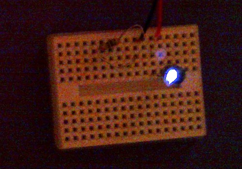
If sending isn't working, first make sure your IR LED is actually transmitting. IR will usually show up on a video camera or cell phone camera, so this is a simple way to check. Try putting the LED right up to the receiver; don't expect a lot of range unless you amplify the output.

The next potential problem is if the receiver doesn't understand the transmitter, for instance if you are sending the wrong data or using the wrong protocol. If you have a remote, use this library to check what data it is sending and what protocol it is using.

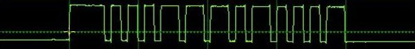
An oscilloscope will provide a good view of what the Arduino or a remote is transmitting. You can use an IR photodiode to see what is getting transmitted; connect it directly to the oscilloscope and hold the transmitter right up to the photodiode. If you have an oscilloscope, just connect the oscilloscope to the photodiode. If you don't have an oscilloscope, you can use a sound card oscilloscope program such as xoscope.

The Sony and RC5/6 protocols specify that messages must be sent three times. I have found that receivers will ignore the message if only sent once, but will work if it is sent twice. For RC5/6, the toggle bit must be flipped by the calling code in successive transmissions, or else the receiver may only respond to a code once.

Finally, there may be bugs in this library. In particular, I don't have anything that receives RC5/RC6, so they are untested.

Problems with Receiving

If receiving isn't working, first make sure the Arduino is at least receiving raw codes. The LED on pin 13 of the Arduino will blink when IR is being received. If not, then there's probably a hardware issue.

If the codes are getting received but cannot be decoded, make sure the codes are in one of the supported protocols. If codes should be getting decoded, but are not, some of the measured times are probably not within the 20% tolerance of the expected times. You can print out the minimum and maximum expected values and compare with the raw measured values.

The examples/IRrecvDump sketch will dump out details of the received data. The dump method dumps out these durations but converts them to microseconds, and uses the convention of prefixing a space measurement with a minus sign. This makes it easier to keep the mark and space measurements straight.

IR sensors typically cause the mark to be measured as longer than expected and the space to be shorter than expected. The code extends marks by 100us to account for this (the value MARK_EXCESS). You may need to tweak the expected values or tolerances in this case.

The library does not support simultaneous sending and receiving of codes; transmitting will disable receiving.
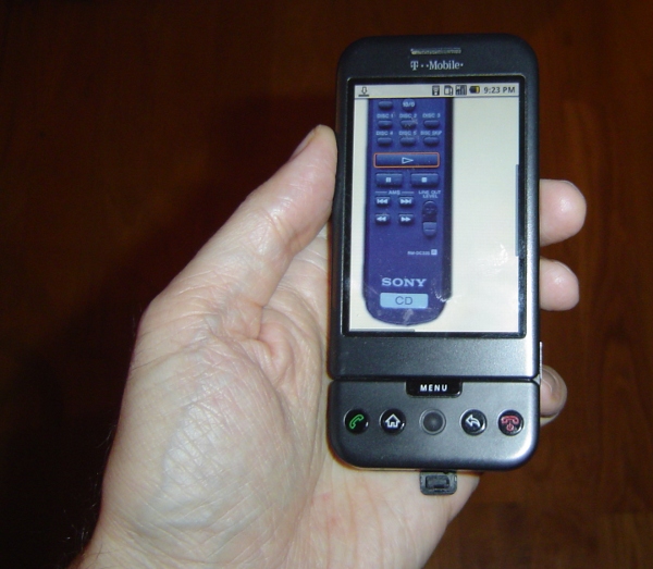
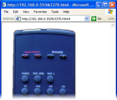
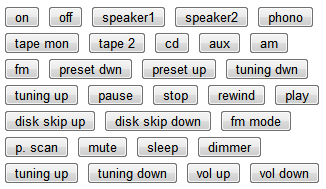
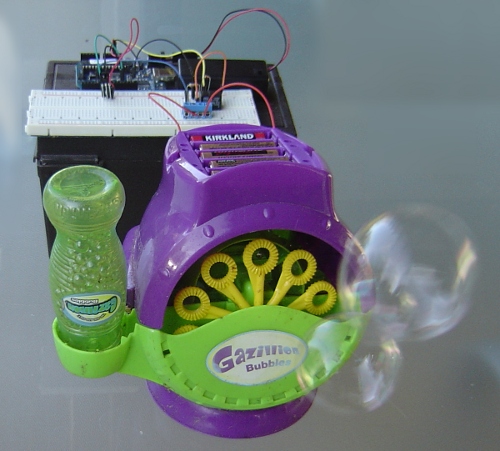
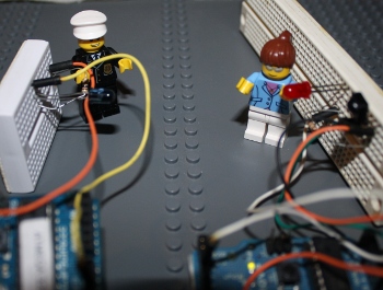
Applications

I've used this library for several applications:

Other projects that use this library

Other Arduino IR projects

I was inspired by Building a Universal Remote with an Arduino; this doesn't live up to being a universal remote, but has a lot of information. The NECIRrcv library provided the interrupt handling code I use.

Four Rigol oscilloscope hacks with Python

A Rigol oscilloscope has a USB output, allowing you to control it with a computer and and perform additional processing externally. I was inspired by Cibo Mahto's article Controlling a Rigol oscilloscope using Linux and Python, and came up with some new Python oscilloscope hacks: super-zoomable graphs, generating a spectrogram, analyzing an IR signal, and dumping an oscilloscope trace as a WAV file. The key techniques I illustrate are connecting to the oscilloscope with Windows, accessing a megabyte of data with Long Memory, and performing analysis on the data.

Analyzing the IR signal from a TV remote using an IR sensor and a Rigol DS1052E oscilloscope.

Analyzing the IR signal from a TV remote using an IR sensor and a Rigol DS1052E oscilloscope.

Super-zoomable graphs

One of the nice features of the Rigol is "Long Memory" - instead of downloading the 600-point trace that appears on the screen, you can record and access a high-resolution trace of 1 million points. In this hack, I show how you can display this data with Python, giving you a picture that you can easily zoom into with the mouse.

The following screenshot shows the data collected by hooking the oscilloscope up to an IR sensor. In the above picture, the sensor is the three-pin device below the screen. Since I've developed an IR library for Arduino, my examples focus on IR, but any sort of signal could be used. By enabling Long Memory, we can download not just the data on the screen, but 1 million data points, allowing us to zoom way, way in. The graph below shows what it sent when you press a button on the TV remote - the selected button transmits a code, followed by a periodic repeat signal as long as the button is held down.

The IR signal from a TV remote. The first block is the code, followed by period repeat signals while the button is held down.

The IR signal from a TV remote. The first block is the code, followed by period repeat signals while the button is held down.
But with Long Memory, we can interactively zoom way on the waveform and see the actual structure of the code - long header pulses followed by a sequence of wide and narrow pulses that indicate the particular button. That's not the end of the zooming - we can zoom way in on an edge of a pulse and see the actual rise time of the signal over a few microseconds. You can do some pretty nice zooming when you have a million datapoints to plot.

Zooming in on the first part of the waveform shows the structure of the code - long header pulses followed by wide and narrow pulses. Zooming way, way in on the edge of a pulse shows the rise time of the signal.

To use this script, first enable Long Memory by going to Acquire: MemDepth. Next, set the trigger sweep to Single. Capture the desired waveform on the oscilloscope. Then run the Python script to upload the data to your computer, which will display a plot using matplotlib. To zoom, click the "+" icon at the bottom of the screen. This lets you pan back and forth through the data by holding down the left mouse button. You can zoom in and out by holding the right mouse button down and moving the mouse right or left. The magnifying glass icon lets you select a zoom rectangle with the mouse. You can zoom on your oscilloscope too, of course, but using a mouse and having labeled axes can be much more convenient.

A few things to notice about the code. The first few lines get the list of instruments connected to VISA and open the USB instrument (i.e. your oscilloscope). The timeout and chunk size need to be increased from the defaults to download the large amount of data without timeouts.

Next, ask_for_values gets various scale values from the oscilloscope so the axes can be labeled properly. By setting the mode to RAW we download the full dataset, not just what is visible on the screen. We get the raw data from channel 1 with :WAV:DATA? CHAN1. The first 10 bytes are a header and should be discarded. Next, the raw bytes are converted to numeric values with Mahto's formulas. Finally, matplotlib plots the data.

There are a couple "gotchas" with Long Memory. First, it only works reliably if you capture a single trace by setting the trigger sweep to "single". Second, downloading all this data over USB takes 10 seconds or so, which can be inconveniently slow.

Analyze an IR signal

Once we can download a signal from the oscilloscope, we can do more than just plot it - we can process and analyze it. In this hack, I decode the IR signal and print the corresponding hex value. Since it takes 10 seconds to download the signal, this isn't a practical way of using an IR remote for control. The point is to illustrate how you can perform logic analysis on the oscilloscope trace by using Python.

This code shows how the Python script can wait for the oscilloscope to be triggered and enter the STOP state. It also shows how you can use Python to initialize the oscilloscope to a desired configuration. The oscilloscope gets confused if you send too many commands at once, so I put a short delay between the commands.

Generate a spectrogram

Another experiment I did was using Python libraries to generate a spectrogram of a signal recorded by the oscilloscope. I simply hooked a microphone to the oscilloscope, spoke a few words, and used the script below to analyze the signal. The spectrogram shows low frequencies at the bottom, high frequencies at the top, and time progresses left to right. This is basically a FFT swept through time.

A spectrogram generated by matplotlib using data from a Rigol DS1052E oscilloscope.

A spectrogram generated by matplotlib using data from a Rigol DS1052E oscilloscope.
To use this script, set up the oscilloscope for Long Memory as before, record the signal, and then run the script.

Dump data to a .wav file

You might want to analyze the oscilloscope trace with other tools, such as Audacity. By dumping the oscilloscope data into a WAV file, it can easily be read into other software. Or you can play the data and hear how it sounds.

To use this script, enable Long Memory as described above, capture the signal, and run the script. A file channel1.wav will be created.

How to install the necessary libraries

Before connecting your oscilloscope to your Windows computer, there are several software packages you'll need.
  • I assume you have Python already installed - I'm using 2.7.3.
  • Install NI-VISA Run-Time Engine 5.2. This is National Instruments Virtual Instrument Software Architecture, providing an interface to hardware test equipment.
  • Install PyVISA, the Python interface to VISA.
  • If you want to run the graphical programs, install Numpy and matplotlib.
You can also use Rigol's UltraScope for DS1000E software, but the included NI_VISA 4.3 software doesn't work with pyVisa - I ended up with VI_WARN_CONFIG_NLOADED errors. If you've already installed Ultrascope, you'll probably need to uninstall and reinstall NI_VISA.

If you're using Linux instead of Windows, see Mehta's article.

How to control and program the oscilloscope

Once the software is installed (below), connect the oscilloscope to the computer's USB port. Use the USB port on the back of the oscilloscope, not the flash drive port on the front panel.

Hopefully the code examples above are clear. First, the Python program must get the list of connected instruments from pyVisa and open the USB instrument, which will have a name like USB0::0x1AB1::0x0588::DS1ED141904883. Once the oscilloscope connection is open, you can use scope.write() to send a command to the oscilloscope, scope.ask() to send a command and read a result string, and scope.ask_for_values() to send a command and read a float back from the oscilloscope.

When the oscilloscope is under computer control, the screen shows Rmt and the front panel is non-responsive. The "Force" button will restore local control. Software can release the oscilloscope by sending the corresponding ":KEY:FORCE" command.

Error handling in pyVisa is minimal. If you send a bad command, it will hang and eventually timeout with VisaIOError: VI_ERROR_TMO: Timeout expired before operation completed.

The API to the oscilloscope is specified in the DS1000D/E Programming Guide. If you do any Rigol hacking, you'll definitely want to read this. Make sure you use the right programming guide for your oscilloscope model - other models have slightly different commands that seem plausible, but they will timeout if you try them.

Conclusions

Connecting an oscilloscope to a computer opens up many opportunities for processing the measurement data, and Python is a convenient language to do this. The Long Memory mode is especially useful, since it provides extremely detailed data samples.

Control your mouse with an IR remote

You can use an IR remote to control your computer's keyboard and mouse by using my Arduino IR remote library and a small microcontroller board called the Teensy. By pushing the buttons on your IR remote, you can steer the cursor around the screen, click on things, and enter digits. The key is the Teensy can simulate a USB keyboard and mouse, and provide input to your computer.

How to do this

I built a simple sketch that uses the remote from my DVD player to move and click the mouse, enter digits, or page up or down. Follow these steps:
  • The hardware is nearly trivial. Connect a IR detector to the Teensy: detector pin 1 to Teensy input 11, detector pin 2 to ground, and detector pin 3 to +5 volts.
  • Install the latest version of my IR remote library, which has support for the Teensy.
  • Download the IRusb sketch.
  • In the Arduino IDE, select Tools > Board: Teensy 2.0 and select Tools > USB Type: Keyboard and Mouse.
  • Modify the sketch to match the codes from your remote. Look at the serial console as you push the buttons on your remote, and modify the sketch accordingly. (This is explained in more detail below.)
To reiterate, this sketch won't work on a standard Arduino; you need to use a Teensy.

How the sketch works

The software is straightforward because the Teensy has USB support built in. First, the IR library is initialized to receive IR codes on pin 11:
#include <IRremote.h>

int RECV_PIN = 11;
IRrecv irrecv(RECV_PIN);
decode_results results;

void setup()
{
  irrecv.enableIRIn(); // Start the receiver
  Serial.begin(9600);
}
Next, the decode method is called to receive IR codes. If the hex value for the received code corresponds to a desired button, a USB mouse or keyboard command is sent. If a code is not recognized, it is printed on the serial port. Finally, after receiving a code, the resume method is called to resume receiving IR codes.
int step = 1;
void loop() {
  if (irrecv.decode(&results)) {
    switch (results.value) {
    case 0x9eb92: // Sony up
      Mouse.move(0, -step); // up
      break;
    case 0x5eb92:  // Sony down
      Mouse.move(0, step); // down
      break;
...
    case 0x90b92:  // Sony 0
      Keyboard.print("0");
      break;
...
    default:
      Serial.print("Received 0x");
      Serial.println(results.value, HEX);
      break;
    }
    irrecv.resume(); // Resume decoding (necessary!)
  }
}
You may wonder where the codes such as 0x9eb92 come from. These values are for my Sony DVD remote, so chances are they won't work for your remote. To get the values for your remote, look at the serial console as you press the desired buttons. As long as you have a supported remote type (NEC, Sony, RC5/6), you'll get the hex values to put into the sketch. Simply copy the hex values into the sketch, and perform the desired action.

There are a few details to note. If your remote uses the RC5 or RC6 format, there are actually two different codes assigned to each button, and the remote alternates between them. Push the button twice to see if you'll need to use two different codes. If you want to send a non-ASCII keyboard code, such as Page Down, you'll need to use a slightly more complex set of commands (documentation). For example, the following code sends a Page UP if it receives a RC5 Volume Up from the remote. Note that there are two codes for volume up, and note that KEY_PAGE_UP is sent, followed by 0 (no key).

    case 0x10: // RC5 vol up
    case 0x810:
      Keyboard.set_key1(KEY_PAGE_UP);
      Keyboard.send_now();
      Keyboard.set_key1(0);
      Keyboard.send_now();
      break;

Improvements

My first implementation of the sketch as described above was very easy, but there were a couple displeasing things. The first problem was the mouse movement was either very slow (with a small step size) or too jerky (with a large step size). Second, if you press a number on the remote, the keyboard input rapidly repeats because the IR remote repeatedly sends the IR code, so you end up with "111111" when you just wanted "1".

The solution to the mouse movement is to implement acceleration - as you hold the button down, the mouse moves faster. This was straightforward to implement. The sketch checks if the button code was received within 200ms of the previous code. If so, the sketch speeds up the mouse movement by increasing the step size. Otherwise it resets the step size to 1. The result is that tapping the button gives you fine control by moving the mouse a little bit, while holding the button down lets you zip across the screen:

    if (millis() - lastTime > GAP) {
      step = 1;
    } 
    else if (step > 20) {
      step += 1;
    }
Similarly, to prevent the keyboard action from repeating, we only output keypresses if the press is more then 200ms after the previous. This results in a single keyboard action no matter how long a button is pressed down. The same thing is done to prevent multiple mouse clicks.
 if (millis() - lastTime > GAP) {
        switch (results.value) {
        case 0xd0b92:
          Mouse.click();
          break;
        case 0x90b92:
          Keyboard.print("0");
          break;
...

Now you can control your PC from across the room by using your remote. Thanks to Paul Stoffregen of PJRC for porting my IR remote library to the Teensy and sending me a Teensy for testing.

Don't walk! Controlling a pedestrian sign with an Arduino

My latest project is controlling a pedestrian sign with an Arduino, so it will automatically step through the states of walk, flashing don't walk, and solid don't walk. In addition, I added infrared remote control support so I can use a remote control to turn the sign on and off, set it to a particular state, or start the cycle.

The hardware

A pedestrian sign controlled by an Arduino.
The pedestrian sign is controlled by two relays that switch 120-volt AC on and off; one powers the "walk" part of the sign, and one powers the "don't walk" part.
The Arduino circuitry.
The Arduino drives the relays through transistors connected to 9-volt supply. Technically the relays are 12-volt relays, but they seem to work with 9 volts. I used one 10A relay, and one 5A relay, just because that's what I had around.
The relays controlling the sign.
Needless to say, 120 volts can be dangerous, both to yourself and to your Arduino. Follow the appropriate precautions. I make no claims about the safety of this circuit.

The remote control input uses an IR detector module connected to the Arduino. For details on the IR detection, see the article on my IRremote library. The code section below describes how to modify the code to support different remotes.
Schematic of the pedestrian sign controller.

I found the IR detector didn't work super-reliably when the sign was turned on. This was probably due to high-frequency electrical interference since adding some capacitors helped, but the light itself could have been interfering. I probably should have wired up the relay circuit and the IR detector circuit farther apart to minimize interference, as I did when controlling a DC motor.

Inside the pedestrian sign

You may be curious about what's inside a pedestrian sign. What I have is the lighting unit; this goes inside the metal case that you see attached to a traffic pole. (In case you're worried, I didn't steal this from an intersection. I got it on ebay from some city that was replacing their units with more efficient LED units.)

Inside the signal are two neon tubes, roughly the shape of the hand and the pedestrian; generating red and white light respectively. I use "neon tube" in the generic sense; I don't know what gas is actually inside. Note that the tubes are not colored and the cover is clear; the red color is entirely from the gas discharge.
The neon tubes the pedestrian sign
Beneath the tubes are two high-voltage driver circuits, one for each tube. Each driver circuit runs off 120V AC and has an oscillator (using a LM2903 comparator) driving a flyback transformer through a power transistor (under the board). This generates multi-kilovolts to drive the tubes. Note at the far left the standoffs that keep the output wire an inch above the circuit board due to the high voltage. Needless to say, I stay away from the circuitry while it is operating. Each driver board has a separate AC input; when AC is fed in, the tube lights up. One drawback of the driver circuitry is it makes a high-pitched whine when turned on. I originally planned to use the sign to indicate unittest pass/fail status, but it was too annoying to people nearby.
The power circuits for the pedestrian sign

The code

The Arduino code is available at IRtraffic.pde and has two main functions: IR processing and light cycle processing.

In the IR code, the IR remote is used to select one of five states: walk illuminated, blinking don't walk, don't walk illuminated, off, or cycling (which goes through the first three states). The IR functionality uses my IRremote library to decode the output from a remote control.

The code has the values for a particular remote control hard-coded. I used a Sony DVD remote:

#define OFF_CODE 0x1CB92 // Stop on Sony DVD remote
#define WALK_CODE 0xB92 // 1 on Sony DVD remote
#define BLINK_CODE 0x80b92 // 2 on Sony DVD remote
#define DONT_CODE 0x40b92 // 3 on Sony DVD remote
#define CYCLE_CODE 0x4CB92 // Play on Sony DVD remote
The first part of the loop function calls the IR library to see if an IR signal has been decoded. If so, it switches to the appropriate mode. If an unexpected IR value is encountered, it is printed to the serial port.
void loop() {
  // Process the IR input, if any
  if (irrecv.decode(&results)) {
    if (results.value == WALK_CODE) {
      Serial.write("Walk\n");
      mode = MODE_WALK;
      cycle = false;
    } 
    else if (results.value == DONT_CODE) {
      Serial.write("Don't walk\n");
      mode = MODE_DONT;
      cycle = false;
    } 
    else if (results.value == OFF_CODE) {
      Serial.write("Off\n");
      mode = MODE_OFF;
      cycle = false;
    } 
    else if (results.value == BLINK_CODE) {
      Serial.write("Blinking don't walk\n");
      mode = MODE_BLINK;
      blinkOn = true;
      nextBlinkMillis = millis() + 500; // 500 ms blink
      cycle = false;
    } 
    else if (results.value == CYCLE_CODE) {
      Serial.write("Cycle\n");
      nextCycleMillis =  millis() + 5000; // delay 5 seconds
      cycle = true;
      mode = MODE_WALK;
    } 
    else {
      Serial.print("unexpected value: ");
      Serial.println(results.value, HEX);
    }
    irrecv.resume(); // Resume decoding (necessary!)
  }
If you want to use a different remote, simply look at the "unexpected values" printed to the serial port while pressing the desired buttons, copy the hex values into the code, recompile, and reinstall. For instance, to use some Tivo buttons, simply change the button definitions to:
#define OFF_CODE 0x20df10ef
#define WALK_CODE 0xa10cd00f
#define BLINK_CODE 0xa10c8807
#define DONT_CODE  0xa10cc807
#define CYCLE_CODE 0xa10c6c03
The other main function of the code is timing. There are two timing cycles going on. First, if cycle mode is enabled, the mode is advanced through walk, blink, and don't walk every five seconds. Second, if in the blinking don't walk phase, the output is turned on or off every half second.

I originally used delays of 500 or 1000 ms for the timing, but this had the disadvantage that the light wasn't very responsive to the remote control - it would wait up to 1 second before processing the remote control value. I rewrote the code using the BlinkWithoutDelay approach. In this approach, there are no delays in the loop code. Instead, the millis() value is checked to see if it is time to change state. If nothing needs to be done, loop() ends without any delay.

In more detail, the boolean cycle is true if the light is to cycle between the three phases. In this case, nextCycleMillis is set to the time at which we move to the next cycle (i.e. 5 seconds in the future). Once we reach that time, the mode is advanced. The boolean blinkOn keeps track of whether the don't walk sign is on or off while blinking.

  if (cycle && millis() >= nextCycleMillis) {
    if (mode == MODE_WALK) {
      mode = MODE_BLINK;
      blinkOn = false;
      nextBlinkMillis = millis() + 500; // 500 ms blink
      nextCycleMillis = millis() + 5000; // delay 5 seconds
    } 
    else if (mode == MODE_BLINK) {
      mode = MODE_DONT;
      nextCycleMillis =  millis() + 5000; // delay 5 seconds
    } 
    else {
      mode = MODE_WALK;
      nextCycleMillis =  millis() + 5000; // delay 5 seconds
    }
  }
The other independent time is nextBlinkMillis. This is the time at which the don't walk sign should change state, and it is set 500ms into the future.
  if (mode == MODE_BLINK && millis() >= nextBlinkMillis) {
    blinkOn = !blinkOn;
    nextBlinkMillis = millis() + 500; // 500 ms blink
  }
The code may be confusing at first due to the two independent times (nextCycleMillis and nextBlinkMillis) and state variables (mode and blinkOn). It seemed simpler this way rather than folding both cycles into one.

Finally, the code sets the appropriate lights on or off:

  if (mode == MODE_WALK) {
    digitalWrite(DONT_PIN, LOW);
    digitalWrite(WALK_PIN, HIGH);
  } 
  else if (mode == MODE_DONT || (mode == MODE_BLINK && blinkOn)) {
    digitalWrite(DONT_PIN, HIGH);
    digitalWrite(WALK_PIN, LOW);
  } 
  else {
    digitalWrite(DONT_PIN, LOW);
    digitalWrite(WALK_PIN, LOW);
  } 

Conclusion

I have two extra pedestrian signs; I'll give them away for free if you can pick them up in the SF Bay Area.

IR Bubbles: Controlling a relay with an Arduino and an IR remote

An Arduino can be used to turn devices on and off via an infrared remote. As an entirely impractical example of how to use my Arduino infrared remote library to turn things on and off, I have set up my Arduino to turn a bubble maker on and off under remote control. The same techniques can be used to control an LED or anything else via IR remote.

Arduino blowing bubbles

The circuit is straightforward. An IR sensor is connected to the Arduino to detect the infrared signal. On the output side, I used a standard relay circuit. To control the bubble maker, I wired the relay in place of the power switch. A 5 volt source wasn't enough to close the relay I had handy, but 9 volts was. For this reason, I powered the Arduino off a 9V battery and connected the relay to Vin so the relay would get the full 9 volts. (A 9 volt AC adapter also works.)

Arduino IR relay schematic

The code

The following code controls the relay. Any detected IR code will toggle the output on or off. Press a button once on the remote and the output will turn on. Press a button again and the output will turn off. (You will, of course, need to download my Arduino infrared remote library to use this code.)
#include <IRremote.h>

int RECV_PIN = 11;
int OUTPUT_PIN = 4;

IRrecv irrecv(RECV_PIN);
decode_results results;

void setup()
{
  pinMode(OUTPUT_PIN, OUTPUT);
  pinMode(13, OUTPUT);
  irrecv.enableIRIn(); // Start the receiver
}

int on = 0;
unsigned long last = millis();

void loop() {
  if (irrecv.decode(&results)) {
    // If it's been at least 1/4 second since the last
    // IR received, toggle the relay
    if (millis() - last > 250) {
      on = !on;
      digitalWrite(OUTPUT_PIN, on ? HIGH : LOW);
    }
    last = millis();      
    irrecv.resume(); // Receive the next value
  }
}
The above code only toggles the output if there is at least a 1/4 second (250 ms) gap since the last received signal. The motivation behind this is that remotes often repeat the signal as long as the button is held down, and we don't want the output to toggle continuously. One other thing to notice is the call to resume(); after a code is received, the library stops detection until resume() is called.

I should make it clear that although the above example uses a relay output, the relay is just for example. The above code will work with any arbitrary output: you can use it to control a LED or anything else that can be controlled by an Arduino output pin.

Using two buttons

Another way you might want to use an IR remote is have one button turn the output on, and another button turn it off. Here's the loop code to use a Sony DVD remote; the "play" button turns the output on, and the "stop" button turns the output off:
void loop() {
  if (irrecv.decode(&results)) {
    if (results.value == 0x4cb92) { // Sony DVD play
      digitalWrite(OUTPUT_PIN, HIGH);
    } 
    else if (results.value == 0x1cb92) { // Sony DVD stop
      digitalWrite(OUTPUT_PIN, LOW);
    }   
    irrecv.resume(); // Receive the next value
  }
}
Just remember that you have to call resume after all decodes, not just the ones you're interested in.

Getting the codes

You may wonder how I got the Sony codes. One way is to look at the appropriate LIRC config file. (At some point I'll write up a full explanation of the LIRC config files.) An easier way is to just dump out to the serial port the codes that your Arduino receives. Press the buttons on your remote, and read out the values received:
void loop() {
  if (irrecv.decode(&results)) {
    Serial.println(results.value, HEX);
    irrecv.resume(); // Receive the next value
  }
}

Using a specific button

A third way you might want to use an IR remote is to have a specific button toggle the output on and off. Here's code that uses the Tivo button on a Tivo Series 2 remote to toggle the output on and off. Again, you can get the button code from a LIRC config file, or by dumping the output to your serial port.
void loop() {
  if (irrecv.decode(&results)) {
    if (results.value == 0xa10ce00f) { // TIVO button
      // If it's been at least 1/4 second since the last
      // IR received, toggle the relay
      if (millis() - last > 250) {
        on = !on;
        digitalWrite(OUTPUT_PIN, on ? HIGH : LOW);
      }
      last = millis();
    }    
    irrecv.resume(); // Receive the next value
  }
}

The hardware setup

Arduino relay circuit

The hardware setup is pretty simple. The above photo shows the IR detector on the left, and the relay on the right. The drive transistor, resistor, and diode are behind the relay, and the blue terminal strip is in front. The black box to the right of the Arduino is a 9V battery holder. The box underneath is just to hold everything up.

You may wonder why I placed the input and output components so far apart, and why I didn't use the protoboard power and ground buses. It turns out that the motor on the bubble maker is a nasty source of RFI interference that would jam the IR detector's signal if the wires to the bubble maker came near the IR detector wiring. Capacitors didn't help, but distance did. Most likely this won't be a problem for you, but I figured I should mention it.

In conclusion, happy hacking with the infrared library. Let me know if you do anything interesting with it!

Understanding Sony IR remote codes, LIRC files, and the Arduino library

This article describes how to understand Sony IR codes and how to get them from the LIRC files. The article is intended to describe codes for use with my Arduino infrared remote library, but the information should be generally applicable. This article is aimed at the hardware hacker and assumes that you are familiar with binary and hexadecimal, so be warned :-)

One key point of this article is that there are three different ways to interpret the same IR signal and turn it into a hex code. Understanding these three ways will allow you to get codes from different sources and understand them correctly.

The IR transmission of the code

When you press a button on a Sony remote control, an infrared signal is transmitted. This transmission consists of a 40kHz signal which is turned on and off in a particular pattern. Different buttons correspond to different codes, which cause the signal to be turned on and off in different patterns.

The following waveform shows the IR code transmitted for STOP on my Sony CD remote control (RM-DC335). When the signal is high, a 40 kHz IR signal is transmitted, and when the signal is low, nothing is transmitted. In other words, the signal is actually rapidly turning on and off when it appears to be on in the figure. (The IR receiver demodulated the signal, so you don't see the 40 kHz transitions.)
IR transmission for a Sony remote control
A Sony IR signal starts with 2400 microseconds on and 600 microseconds off; that's the first wide pulse. A "1" bit is transmitted with 1200 microseconds on and 600 microseconds off, while a "0" bit is transmitted with 600 microseconds on and 600 microseconds off. (This encoding is also called SIRC or SIRCS encoding.)

You may notice the "on" parts of the waveform appear wider than the "off" parts, even when both are supposed to be 600 microseconds. This is a result of the IR receiver, which switches on faster than switching off.

The above waveform represents one transmission of a 12-bit code. This transmission is normally repeated as long as the button is held down, and a minimum of three times. Each transmission starts 45ms after the previous one started. The Sony protocol also supports 15 and 20 bit codes, which are the same as above except with more bits.

For more information on the low-level transmission of Sony codes, see sbprojects.net.

Three ways to interpret the codes

The Sony encoding seems straightforward, but there are several different ways the signal can be interpreted. I will call these official decoding, bit decoding, and bit-1 decoding. Different sources use any of these three, which can cause confusion. I will explain these three decodings, using the previous waveform as an example.

Official decoding

Official Sony decoding
The "official" Sony protocol views the 12-bit code as 7 command bits and 5 address or device bits, transmitted least-significant-bit first (i.e. "backwards"). The device bits specify the type of device receiving the code, and the command bits specify a particular command for this device. In this example, the device bits (yellow) are 10001 when read right-to-left, which is 17 decimal. The command bits (blue) are 0111000 when read right-to-left, which is 56 decimal. The device value 17 corresponds to a CD player, and the command 56 corresponds to the STOP command (details).

Sony 15 bit codes are similar, with 7 command bits and 8 device bits. Sony 20 bit codes have 7 command bits, 5 device bits, and 8 extended device bits.

Bit decoding

Decoding Sony IR code as a sequence of bits
Many IR decoders just treat the signal as a sequence of bits, most-significant-bit first. I will call this bit decoding. Applying this interpretation to the above code, the code is interpreted as 0001 1101 0001 binary, or 1d1 hex, or 465 in decimal. Note that the last bit doesn't really consist of 1200 microseonds on and 600 microseconds off; it consists of 1200 microseconds on followed by a lot of time off. In other words, the transmission is off for 600 microseconds and then continues to be off until the next code is transmitted.

An alternative but equivalent interpretation is to view the code as a 2400 microsecond header, followed by 12 bits, where each bit is off then on (rather than on then off). A "1" bit is 600 microseconds off and 1200 microseconds on, while a "0" bit is 600 microseconds off and 600 microseconds on. This yields the same value as before (232 decimal), but avoids the special handling of the last bit.
Short one bit decoding

Bit-1 decoding

Short one bit decoding
Many IR decoders drop the last bit, which I will call bit-1 decoding. Because the last bit doesn't end nicely with 600 microseconds off, some IR decoding algorithms treat the signal as 11 bits of data, ending with 600 microseconds on as a trailer. In this interpretation, the above code is 000 1110 1000 binary, or 0e8 hex, or 232 decimal. (Note that doubling this value and adding 1 yields the previous decoding of 465.)

Discussion

Is the code really 17/44 or 465 or 232? The official decoding is "right" in the sense that it is what the manufacturer intends. In addition, it reveals the internal structure of the code and the codes make more sense. For instance, the buttons 1-9 have consecutive codes with the official decoding, but not with the others. The other decodings are fine to use as long as you're consistent; the main thing is to understand that different sources use different decodings. My Arduino library uses the second bit decoding interpretation. The different decodings can be converted from one form to another with binary arithmetic.

Getting codes from a remote

Probably the easiest way to get the codes for your device is to use your existing remote control and see what codes it transmits. You can use my Arduino IR library to do the decoding, with the IRrecvDump demo program. Take a 3-pin IR decoder, hook it up to an Arduino, and then you can read the values for each button press on the serial port.

Alternatively, you can look at the transmitted codes with an oscilloscope. For the diagrams above, I used an IR receiver module connected to two resistors (to drop the voltage), connected to the line input of my PC. I used the Zeitnitz Soundcard Oscilloscope program to display the signal. This lets you see exactly what is being transmitted, but you will need to stare at the screen, write down a bunch of 0's and 1's, and convert the binary value to get your codes.

Getting codes from LIRC files

The best source for IR codes that I've found is the Linux Infrared Remote Control project (lirc.org), which has a huge collection of config files for various remotes. (LIRC also includes a large collection of device drivers for many types of IR input/output hardware, and a software library.)

The LIRC config file format is documented at WinLIRC, but I will walk through some examples.

Bit decoding

The RM-S530 LIRC file treats the codes as 12 bits long, using what I call bit decoding:
begin remote

  name  Sony
  bits           12
  flags SPACE_ENC|CONST_LENGTH
  eps            30
  aeps          100

  header       2470   557
  one          1243   556
  zero          644   556
  gap          45076
  min_repeat      2
  toggle_bit      0


      begin codes
          sleep                    0x0000000000000061
          cd_stop                  0x00000000000001D1
...
This file indicates that each entry is 12 bits long. A header consists of on for 2470 microseconds and off for 557 microseconds. A one bit consists of on for 1243 microseconds and off for 556 microseconds. A zero bit consists of on for 644 microseconds and off for 556 microseconds. Codes are repeated a minimum of 2 more times, with a gap of 45076 microseconds from start to start as the codes are constant length (CONST_LENGTH).

You may be wondering why these time values don't match the official values of 2400, 1200, and 600 microseconds. First, the LIRC data is generally measured from actual remotes, so the real-world timings don't quite match the theory. Second, IR sensors have some lag in detecting "on" and "off", and they typically stretch out the "on" time by ~100 microseconds, shortening the "off" time equally.

The LIRC file then lists the hex code associated with each button. For example the CD STOP code is hex 1D1, which is the same value as described earlier.

Bit-1 decoding

The LIRC file for the RM-D302 remote treats the codes as 11 bits and a trailing pulse. This is what I call the bit-1 decoding:
begin remote

  name  RM-D302
  bits           11
  flags SPACE_ENC|CONST_LENGTH
  eps            30
  aeps          100

  header       2367   638
  one          1166   637
  zero          565   637
  ptrail       1166
  gap          45101
  min_repeat      2
  toggle_bit      0


      begin codes
          cd_stop                  0x00000000000000E8
The key differences with the previous file are the ptrail field, indicating a trailing pulse of 1166 microseconds; and the bit count of 11 instead of 12. Note that the code value is different from the first file, even thought the IR transmission is exactly the same. The hex code 0E8 is the same as described earlier under bit-1 decoding.

Pre_data and post_data bits

Some LIRC files break apart the codes into constant pre_data bits, the code itself, and constant post_data bits. For instance, the file for my RM-D335 remote:
begin remote

  name  SONY
  bits            7
  flags SPACE_ENC
  eps            20
  aeps            0

  header       2563   520
  one          1274   520
  zero          671   520
  ptrail       1274
  post_data_bits  4
  post_data      0x8
  gap          25040
  min_repeat      2

      begin codes
          CONTINUE                 0x000000000000005C
...
          STOP                     0x000000000000000E
...
This file indicates that each code entry is 7 bits long, but there are also 4 post data bits. This means that after transmitting the 7 bits for the code, 4 additional bits are transmitted with the "post data" hex value 0x8, i.e. 1000 binary.

Putting this together the STOP button has the hex value 0E, which corresponds to the seven bits 000 1110. This is followed by four post data bits 1000, so the total transmission is the eleven bits 000 1110 1000, which is 0E8 hex, the same as before for the bit-1 decoding.

One more thing to notice in this LIRC file is it doesn't have the CONST_LENGTH flag, and the gap is 25ms instead of 45ms. This indicates the gap is from the end of one code to the start of the next, rather than from the start of one code to the start of the next. Specifying a gap between codes isn't how Sony codes are actually defined, it's close enough.

LIRC summary

Note that these LIRC files all indicate exactly the same IR transmission; they just interpret it differently. The first file defines the STOP code as 1D1, the second as E8, and the third as 0E.

What does this mean to you? If you want to get a Sony code from a LIRC file and use it with the Arduino library, you need to have a 12 bit (or 15 or 20 bit) code to pass to the library (bit decoding). Look up the code in the file and extract the specified number of bits. If there are any pre_data or post_data bits, append them as appropriate. If the result is one bit short and the LIRC file has a ptrail value, append a 1 bit on the end to convert from bit-1 decoding to bit decoding. Convert the result to hex and you should have the proper code for your device, that can be used with the Arduino library.

Getting codes from hifi-remote.com

The most detailed site I've found on Sony codes specifically is hifi-remote.com/sony. An interesting thing about this site is it analyzes the structure of the codes. While the LIRC files just list the codes, the hifi-remote site tries to explain why the codes are set up the way they are.

Note that this site expresses codes in Sony format, i.e. most-significant-bit first, and separating the device part of the code from the command part of the code. Also for a 20-bit Sony code, the 13 bit device code is expressed as a 5 bit value and an 8 bit value separated by a period. As a result, you may need to do some binary conversion and reverse the bits to use these codes.

To work through an example, I can look up the data for a Sony CD. There are multiple device codes, but assume for now I know my device code is 17. The table gives the code 56 for STOP. Convert 56 to the 7 bit binary value 0111000 and reverse it to get 0001110. Convert 17 to the 5 bit binary value 10001 and reverse it to get 10001. Put these together to et 000111010001, which is 1D1 hex, as before.

To work through a 20-bit example, if I have a Sony VCR/DVD Combo with a device code of 26.83, the site tells me that the code for "power" is 21. Convert 21 to a 7 bit binary value, 26 to a 5 bit binary value, and 83 to a 8 bit binary value. Then reverse and concatenate the bits: binary 1010100 + 01011 + 11001010, which is a8bca in hex. To confirm, the RMT-V501A LIRC file lists power as A8B with post_data of CA.

To use this site, you pretty much have to know the device code for your device already. To find that, obtain a code for your device (e.g. from your existing remote or from LIRC), split out and reverse the appropriate bits, and look up the device code on the site. Alternatively, there are only a few different device codes for a particular type of device, so you can just try them all and see what works.

This site also has information on "discrete codes". To understand discrete codes, consider the power button on a remote that toggles between "on" and "off". This may be inconvenient for automated control, since without knowing the current state, you don't know if sending a code will turn the device on or off. The solution is the "discrete code", which provides separate "on" and "off" codes. Discrete codes may also be provided for operations such as selecting an input or mode. Since these codes aren't on the remote, they are difficult to obtain.

Other sites

Additional config files are available at irremote.psiloc.com. These are in LIRC format, but translated to XML. The site remotecentral.com has a ton of information on remotes, but mostly expressed in proprietary formats.

Conclusion

Hopefully this will clear up some of the confusion around Sony remote codes, without adding additional confusion :-)

Detecting an IR Beam Break with the Arduino IR Library

One reader asked how to use my Arduino Infrared Library to detect breakage of an IR beam. The answer was too long for the comments section, so I've extended into a blog post. One straightforward way is to use the library to modulate an IR LED at 38kHz, and use a standard IR detector module to detect the signal. The output from the module can be simply read as a digital input.

Here is a simple sketch to do that. The IR LED is connected to pin 3 through a 100 ohm resistor, the detector is connected to pin 2, and a status LED is connected to pin 13 (if your Arduino board doesn't have it already.) To create the modulated output, simply call irsend.enableIROut(38); to set the PWM to 38kHz, and then irsend.mark(0) to send a mark (i.e. turn the output on). The loop simply reads the input from the detector, inverts it (since the detector is active-low), and writes it to the status LED.

#include <IRremote.h>

#define PIN_IR 3
#define PIN_DETECT 2
#define PIN_STATUS 13

IRsend irsend;
void setup()
{
  pinMode(PIN_DETECT, INPUT);
  pinMode(PIN_STATUS, OUTPUT);
  irsend.enableIROut(38);
  irsend.mark(0);
}

void loop() {
  digitalWrite(PIN_STATUS, !digitalRead(PIN_DETECT));
}
You should see the pin 13 LED light up when the IR receiver detects an infrared signal, and go dark when the receiver does not detect an infrared signal. The circuit is basically trivial, but there's a schematic at my original article if you need one. The following picture shows the detector setup. Note the illuminated status LED.
IR detector circuit
If the circuit doesn't work, first use a cell phone camera to verify that the infrared LED is lit. If the LED is not lit, try reversing it. Here's my cellphone's view of the illuminated LED:
illuminated infrared LED
Next, point a TV remote control at the detector and make sure the status LED flashes. If the status LED doesn't come on, make sure you wired the detector properly, and connected to input 2 of the Arduino. If the status LED won't turn off when you break the beam, you probably aren't blocking the IR signal well enough. The detector is very sensitive, and IR bounces off many things, so you may need to separate the LED and detector by several feet and make sure you're fully blocking the IR beam. Note that the library assumes you're using a ATmega168/328, so you're on your own if you have a different processor.

The tricky part of this is the optics - figuring out how to set up the LED and receiver so the beam gets interrupted when you want it to. Also, you'll probably want to modify the detection logic to do something more interesting than just set the status LED, but that's left as an exercise for the reader :-)

TV-B-Gone for the Arduino

I've ported the TV-B-Gone code to run on the Arduino board. If you haven't seen a TV-B-Gone, it's a cute gadget that you point at a TV that's bothering you, and it turns the TV off. Internally, it's an infrared remote that broadcasts more than 100 different off codes that work on almost any TV. I figured it would be interesting to get the TV-B-Gone running on the Arduino.
TV-B-Gone running on an Arduinio

Update (November 2010)

I have a new, improved version of the software. Details and download are here.

The software

I started with the TV-B-Gone firmware, which is available under Creative Commons license. The TV-B-Gone runs on an ATtiny85 microcontroller, not the ATmega328 used by the Arduino, so some porting was required. One tricky part of the port is the IR signals are generated using the low-level hardware timer for PWM (pulse-width modulation). Since the ATtiny85 runs at 8MHz, and the Arduino runs at 16MHz, the timing code needed to be re-written, both the 10us delay loop and the timer register operations. The quick summary is I'm using Timer 2, scaling the clock by 8, using OCR2A to control the frequency and OCR2B to control the duty cycle, and have output on pin 3 (OC2B). (You are not expected to understand this. See my article on Secrets of Arduino PWM for details of how these timers work.)
#define freq_to_timerval(x) (F_CPU / 8 / x - 1)
...
    pinMode(IRLED, OUTPUT);
    TCCR2A = _BV(COM2A0) | _BV(COM2B1) | _BV(WGM21) | _BV(WGM20);
    TCCR2B = _BV(WGM22) | _BV(CS21);
...
    OCR2A = freq; 
    OCR2B = freq / 3; // 33% duty cycle
Another tricky thing is the original firmware stores the IR codes in program space, not RAM. The microcontrollers use a Harvard architecture, which means they have separate memory and data paths for code and data, unlike normal processors that use a von Neumann architecture. Because RAM storage is so small on these microcontrollers, the IR codes are stored in program space, with the result you need to use special methods to access them, rather than normal C pointers. Program memory storage is indicated with the PROGMEM macro and pulled out of memory using special functions such as pgm_read_byte. This makes the code somewhat confusing, for example:
const struct IrCode *NApowerCodes[] PROGMEM = {
  &code_na000Code,
...
}

data_ptr = (PGM_P)pgm_read_word(NApowerCodes+i);  

The original firmware stores the codes as compressed indices into tables of durations. See the TV-B-Gone design for details. Unfortunately, the Arduino's compiler didn't like the zero-length array in the IrCode structure, so I needed to rewrite the long file of codes to include another level of indirection.

Apart from these factors, porting was straightforward, and I tried to keep the original code where possible. I ripped out all the power-up and watchdog code. I replaced the low-level serial code with the Arduino's Serial library. Finally, I packaged it up into an Arduino sketch, which you can download. (Update: get the improved version here.)

The hardware

The hardware is straightfoward. I use pin 13 for the status LED; some Arduinos conveniently have an LED already wired up. Pin 3 is the PWM output to the IR LED through a 100 ohm resistor. If you want more range, add a driver transistor and use multiple IR LEDs. Pin 0 (update: pin 5) selects North American or European codes; leave it unconnected for North America and ground it for European. Pin 1 (update: 2) is connected via a pushbutton to ground to trigger the code transmission. (Update: pins have changed in the new version.)

To use the Arduino TV-B-Gone, point the IR LED at your TV, push the button, and your TV should turn off when the circuit hits the right code, which could take up to a minute. The visible LED should flash for each code that is transmitted. If the circuit doesn't work, use a cellphone camera to verify that the IR LED is transmitting. Don't expect more than a few feet range unless you use a transistor to increase the power. The code will print debugging output to the serial port if you set DEBUG in main.h.

Summary

Is the Arduino TV-B-Gone practical? If you want a TV-B-Gone that you can carry around to amaze your friends, the kit or product is much more compact, has high-powered IR outputs for longer range, and is nicely packaged. However, the Arduino platform is convenient for experimenting, and many people already have it, so I expect people will find it interesting.

You might wonder why I'm not using my Arduino Infrared Library for this project. Actually, I plan to at some point, but I wanted to get the straightforward port working first. In addition, my library will need some extensions to support all the codes that the TV-B-Gone supports.

I hope you enjoy the Arduino TV-B-Gone, and remember to use it for good, not evil!

Testing the Arduino IR remote library

I wrote an IR remote library for the Arduino (details) that has turned out to be popular. I want to make sure I don't break things as I improve the library, so I've created a test suite that uses a pair of Arduinos: one sends data and the other receives data. The receiver verifies the data, providing an end-to-end test that the library is working properly.

Overview of the test

The first Arudino repeatedly sends a bunch of IR codes to the second Arduino. The second Arduino verifies that the received code is what is expected. If all is well, the second Arduino flashes the LED for each successful code. If there is an error, the second Arudino's LED illuminates for 5 seconds. The test cycle repeats forever. Debugging information is output to the second Arduino's serial port, which is helpful for tracking down the cause of errors.

Hardware setup

The test hardware is pretty simple: one Arduino transmits, and one Arduino receives. An IR LED is connected to pin 3 of the first Arduino to send the IR code. An IR detector is connected to pin 11 of the second Arduino to receive the IR code. A LED is connected to pin 3 of the second Arduino to provide the test status.
schematic of test setup

Details of the test software

One interesting feature of this test is the same sketch runs on the sending Arduino and the receiving Arduino. The test looks for an input on pin 11 to decide if it is the receiver:
void setup()
{
  Serial.begin(9600);
  // Check RECV_PIN to decide if we're RECEIVER or SENDER
  if (digitalRead(RECV_PIN) == HIGH) {
    mode = RECEIVER;
    irrecv.enableIRIn();
    pinMode(LED_PIN, OUTPUT);
    digitalWrite(LED_PIN, LOW);
    Serial.println("Receiver mode");
  } 
  else {
    mode = SENDER;
    Serial.println("Sender mode");
  }
}
Another interesting feature is the test suite is expressed very simply:
  test("SONY4", SONY, 0x12345, 20);
  test("SONY5", SONY, 0x00000, 20);
  test("SONY6", SONY, 0xfffff, 20);
  test("NEC1", NEC, 0x12345678, 32);
  test("NEC2", NEC, 0x00000000, 32);
  test("NEC3", NEC, 0xffffffff, 32);
...
Each test call has a debugging string, the type of code to send/receive, the value to send/receive, and the number of bits.

On the sender, the testmethod sends the code, while on the receiver, the method verifies that the proper code is received. The SENDER code calls the appropriate send method based on the type, and then delays before the next test. The RECEIVER code waits for a code. If it's correct, it flashes the LED. Otherwise, it sets the state to ERROR.

void test(char *label, int type, unsigned long value, int bits) {
  if (mode == SENDER) {
    Serial.println(label);
    if (type == NEC) {
      irsend.sendNEC(value, bits);
    } 
    else if (type == SONY) {
...
    }
    delay(200);
  } 
  else if (mode == RECEIVER) {
    irrecv.resume(); // Receive the next value
    unsigned long max_time = millis() + 30000;
    // Wait for decode or timeout
    while (!irrecv.decode(&results)) {
      if (millis() > max_time) {
        mode = ERROR; // timeout
        return;
      }
    }
    if (type == results.decode_type && value == results.value && bits == results.bits) {
      // flash LED
    } 
    else {
      mode = ERROR;
    }
  }
}
The trickiest part of the code is synchronizing the sender and the receiver. This happens in loop(). The receiver waits for 1 second without any transmission, while the sender pauses for 2 seconds after each time through the tests. Thus, the receiver will wait while the sender is running through tests, and then will start listening just before the sender starts the next cycle of tests. One other thing to point out is if there is an error, the receiver will skip through all the remaining tests, light the LED to indicate the error, and then will wait to sync up again. This avoids the problem of one bad test getting the receiver permanently out of sync; the receiver is able to re-sync and continue successfully after a failed test.
void loop() {
  if (mode == SENDER) {
    delay(2000);  // Delay for more than gap to give receiver a better chance to sync.
  } 
  else if (mode == RECEIVER) {
    waitForGap(1000);
  } 
  else if (mode == ERROR) {
    // Light up for 5 seconds for error
    mode = RECEIVER;  // Try again
    return;
  }
The test also includes some raw mode tests. These are a bit more complicated, since I want to test the various combinations of sending and receiving in raw mode.

Download and running

I'm gradually moving my development to GitHub at https://github.com/shirriff/Arduino-IRremote.

The code fragments above have been slightly abbreviated; the full code for the test sketch is here.

To download the library and try out the two-Arduino test:

  • Download the IRremote library zip file.
  • Unzip the download
  • Move/rename the shirriff-Arduino-IRremote-nnnn directory to arduino-000nn/libraries/IRremote. The test sketch is in examples/IRtest2.

To run the test, install the sketch on two Arduinos. The test should automatically start running. Note that it is a bit tricky to use two Arduinos at once. They will probably get assigned different serial ports, and you can switch ports using the Tools menu. If you get confused, you can plug one Arduino in at a time, and then you can be sure about which one is getting installed.

My plan is to do more development on the library, now that I have a reasonably solid test suite and I can be more confident that I don't break things. Let me know if there are specific features you'd like.

Thanks go to SparkFun for giving me the second Arduino that made this test possible.

64-bit RC6 codes, Arduino, and Xbox remotes

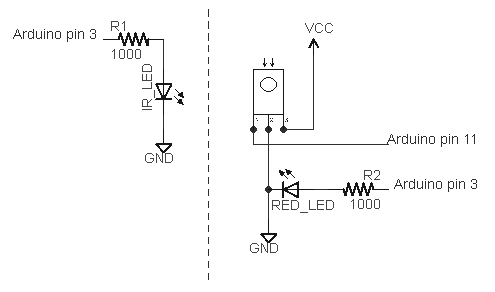
I've extended my Arduino IRremote library to support RC6 codes up to 64 bits long. Now your Arduino can control your Xbox by acting as an IR remote control. (The previous version of my library only supported 32 bit codes, so it didn't work with the 36-bit Xbox codes.) Details of the IRremote library are here.

Note: I don't actually have an Xbox to test this code with, so please let me know if the code works for you.

Download

This code is in my "experimental" branch since I'd like to get some testing before releasing it to the world. To use it:
  • Download the IRremote library zip file from GitHub from the Arduino-IRremote experimental branch.
  • Unzip the download
  • Move/rename the shirriff-Arduino-IRremote-nnnn directory to arduino-000nn/libraries/IRremote.

Sending an Xbox code

The following program simply turns the Xbox on, waits 10 seconds, turns it off, and repeats.
#include <IRremote.h>
IRsend irsend;
unsigned long long OnOff = 0xc800f740cLL;
int toggle = 0;

void sendOnOff() {
  if (toggle == 0) {
    irsend.sendRC6(OnOff, 36);
  } else {
    irsend.sendRC6(OnOff ^ 0x8000, 36);
  }
  toggle = 1 - toggle;
}
   
void setup() {}

void loop() {
  delay(10000);  // Wait 10 seconds
  sendOnOff();  // Send power signal
}
The first important thing to note is that the On/Off code is "unsigned long long", and the associated constant ends in "LL" to indicate that it is a long long. Because a regular long is only 32 bits, a 64-bit long long must be used to hold the 64 bit code. If you try using a regular long, you'll lose the top 4 bits ("C") from the code.

The second thing to notice is the toggle bit (which is explained in more detail below). Every time you send a RC5 or RC6 code, you must flip the toggle bit. Otherwise the receiver will ignore the code. If you want to send the code multiple times for reliability, don't flip the toggle bit until you're done.

Receiving an Xbox code

The following code will print a message on the serial console if it receives an Xbox power code. It will also dump the received value.
#include <IRremote.h>

int RECV_PIN = 11;
IRrecv irrecv(RECV_PIN);
decode_results results;

void setup()
{
  Serial.begin(9600);
  irrecv.enableIRIn(); // Start the receiver
}

void loop() {
  if (irrecv.decode(&results)) {
    if ((results.value & ~0x8000LL) == 0xc800f740cLL) {
      Serial.println("Got an OnOff code");
    }
    Serial.println(results.value >> 32, HEX);
    Serial.println(results.value, HEX);
    irrecv.resume(); // Receive the next value
  }
}
Two things to note in the above code. First, the received value is anded with ~0x8000LL; this clears out the toggle bit. Second, Serial.println is called twice, first to print the top 32 bits, and second to print the bottom 32 bits.

The output when sent power codes multiple times is:

Got an OnOff code
C
800FF40C
Got an OnOff code
C
800F740C
Got an OnOff code
C
...
Note that the received value is split between the two Serial.println calls. Also note that the output oscillates between ...F740C and ...FF40C as the sender flips the toggle bit. This is why the toggle bit must be cleared when looking for a particular value.

The IRremote/IRrecvDump example code has also been extended to display values up to 64 bits, and can be used for testing.

A quick description of RC6 codes

RC6 codes are somewhat more complicated than the usual IR code. They come in 20 or 36 bit varieties (that I know of). The code consists of a leader pulse, a start bit, and then the 20 (or 36) data bits. A 0 bit is sent as a space (off) followed by a mark (on), while a 1 bit is sent as a mark (on) followed by a space (off).

The first complication is the fourth data bit sent (called a trailer bit for some reason), is twice as long as the rest of the bits. The IRremote library handles this transparently.

The second complication is RC5 and RC6 codes use a "toggle bit" to distinguish between a button that is held down and a button that is pressed twice. While a button is held down, a code is sent. When the button is released and pressed a second time, a new code with one bit flipped is sent. On the third press, the original code is sent. When sending with the IRremote library, you must keep track of the toggle bit and flip it each time you send. When receiving with the IRremote library, you will receive one of two different codes, so you must clear out the toggle bit. (I would like the library to handle this transparently, but I haven't figured out a good way to do it.)

For details of the RC6 encoding with diagrams and timings, see SB projects.

The LIRC database

The LIRC project collects IR codes for many different remotes. If you want to use RC6 codes from LIRC, there a few things to know. A typical code is the Xbox360 file, excerpted below:
begin remote
  name  Microsoft_Xbox360
  bits           16
  flags RC6|CONST_LENGTH
  pre_data_bits   21
  pre_data       0x37FF0
  toggle_bit_mask 0x8000
  rc6_mask    0x100000000

      begin codes
          OpenClose                0x8BD7
          XboxFancyButton          0x0B9B
          OnOff                    0x8BF3
...
To use these RC6 code with the Arduino takes a bit of work. First, the codes have been split into 21 bits of pre-data, followed by 16 bits of data. So if you want the OnOff code, you need to concatenate the bits together, to get 37 bits: 0x37ff08bf3. The second factor is the Arduino library provides the first start bit automatically, so you only need to use 36 bits. The third issue is the LIRC files inconveniently have 0 and 1 bits swapped, so you'll need to invert the code. The result is the 36-bit code 0xc800f740c that can be used with the IRremote library.

The rc6_mask specifies which bit is the double-wide "trailer" bit, which is the fourth bit sent (both in 20 and 36 bit RC6 codes). The library handles this bit automatically, so you can ignore it.

The toggle_bit_mask is important, as it indicates which position needs to be toggled every other transmission. For example, to transmit OnOff you will send 0xc800f740c the first time, but the next time you will need to transmit 0xc800ff40c.

More details of the LIRC config file format are at WinLIRC.

Xbox codes

Based on the LIRC file, the following Xbox codes should work with my library:
OpenClose0xc800f7428XboxFancyButton0xc800ff464OnOff0xc800f740c
Stop0xc800ff419Pause0xc800f7418Rewind0xc800ff415
FastForward0xc800f7414Prev0xc800ff41bNext0xc800f741a
Play0xc800ff416Display0xc800f744fTitle0xc800ff451
DVD_Menu0xc800f7424Back0xc800ff423Info0xc800f740f
UpArrow0xc800ff41eLeftArrow0xc800f7420RightArrow0xc800ff421
DownArrow0xc800f741fOK0xc800ff422Y0xc800f7426
X0xc800ff468A0xc800f7466B0xc800ff425
ChUp0xc800f7412ChDown0xc800ff413VolDown0xc800ff411
VolUp0xc800ff410Mute0xc800ff40eStart0xc800ff40d
Play0xc800f7416Enter0xc800ff40bRecord0xc800f7417
Clear0xc800ff40a00xc800f740010xc800f7401
20xc800ff40230xc800f740340xc800ff404
50xc800f740560xc800ff40670xc800f7407
80xc800ff40890xc800f74091000xc800ff41d
Reload0xc800f741c

Key points for debugging

The following are the main things to remember when dealing with 36-bit RC6 codes:
  • Any 36-bit hex values must start with "0x" and end with "LL". If you get the error "integer constant is too large for 'long' type", you probably forgot the LL.
  • You must use "long long" or "unsigned long long" to hold 36-bit values.
  • Serial.print will not properly print 36-bit values; it will only print the lower 32 bits.
  • You must flip the toggle bit every other time when you send a RC6 code, or the receiver will ignore your code.
  • You will receive two different values for each button depending if the sender has flipped the toggle bit or not.